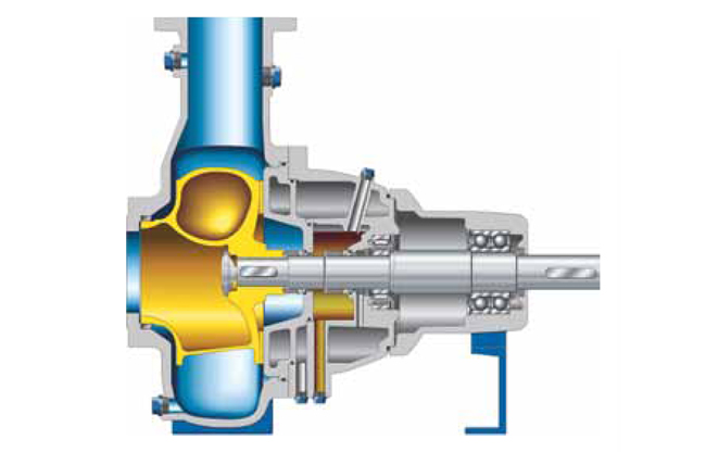
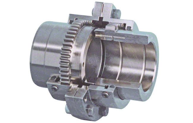
The shaft seal is a
sealing element which seals the rotating
shaft, of a
centrifugal pump where it passes through the non-rotating
pump casing reducing fluidleakage to atmosphere or the entry of air from outside to a certain level, and keeps
wear of the sealing faces as low as possible.
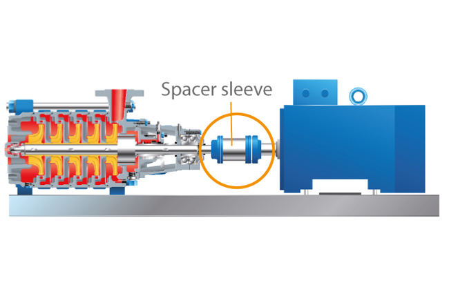
Pumps are specially designed and manufactured to cater for a whole range of different applications. This process takes into account aspects such as resistance to the fluids handled,
temperature and pump pressure. The appropriate seal type for the individual pumping requirements is chosen from a wide variety of different shaft seals.
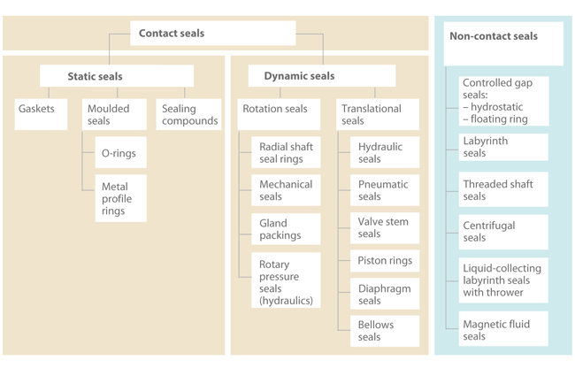
The design is based on one of the two following principles: sealing by means of a narrow radial gap (parallel to the shaft axis) or a narrow axial gap (at a right angle to the shaft axis). For both sealing principles, the gaps may either employ a contact or non-contact design.
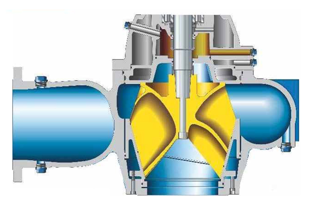
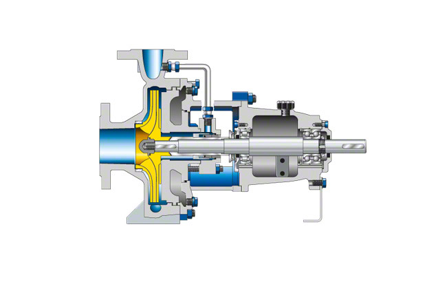
See Fig. 1 Shaft seal
If only non-contacting controlled gap seals are used, a considerable amount of leaking fluid can always be assumed. This sealing system is therefore less suitable for environmentally harmful fluids handled.
Shaft seals are by their nature susceptible to leakage, and with some types leakage is actually essential to ensure proper sealing functioning. The suggestion that a seal shaft provides "zero leakage" is therefore misleading. However, depending on the seal type chosen, the amount of leakage can vary considerably. A
volute casing pump with a
circumferential speed at the sealing area of 20 m/s and a pressure to be sealed of 15 bar which uses a
gland packing for sealing has a leakage rate of about 5 – 8 l/h, while the leakage rate of a
mechanical seal used under the same conditions is only approx. 6 cm
3/h (0.006 l/h).
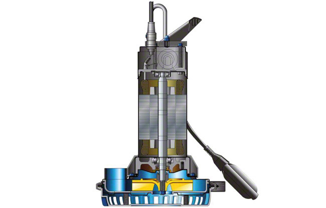
The leakage rate of 4 to 6000 l/h for a
boiler feed pump sealed by a floating ring seal is particularly high; in this case, the diameter to be sealed is 200 mm and the pressure 40 bar, the
rotational speed is 6000 rpm (~ 63 m/s).
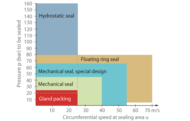
Due to differences in
pump designs the individual seal types are not necessarily suitable for every type of application. The type of seal to be employed depends on the sliding velocity, the
pressure to be sealed and the fluid temperature.
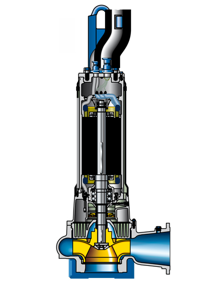
See Fig. 2 Shaft sealContact-type shaft seal
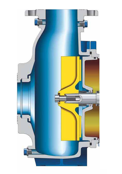
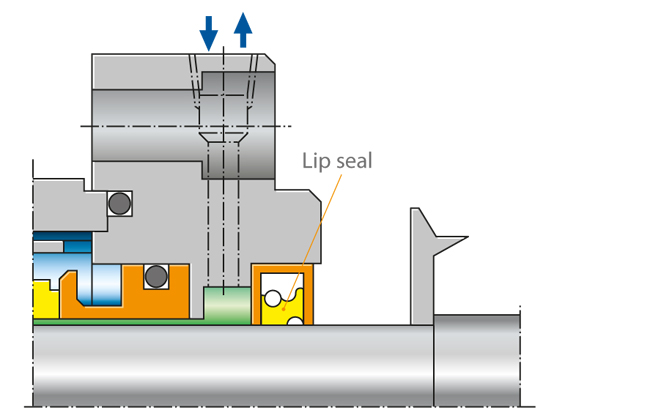
In the case of contact-type dynamic shaft seals, the parts to be sealed move relative to each other. For this reason lip-contact and line-contact shaft seals (e.g. lip seals) are only suitable for use with very low pressure differences such as those occurring when sealing against bearing oil, and are usually not adjustable.
See Fig. 3 Shaft seal
Contact-type shaft seals can be classified as either static or dynamic. Dynamic seal types include gland packings and mechanical seals.
See Fig. 1 Shaft seal
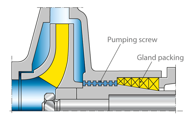
Gland packing
The
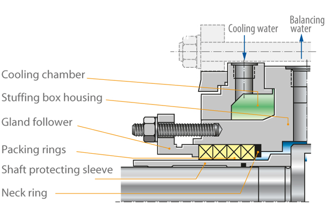
gland packing's application limit is primarily determined by the extent to which heat developing due to friction can be dissipated. For heavy-duty gland packings, leakage water is actually pre-cooled by means of an internally cooled
shaft protecting sleeve and a cooling jacket.
The packing materials generally employed are braided cords made from asbestos-free yarn such as Ramie, Aramid, PTFE, graphite fibres or cotton, which are processed on special machines to form endless square braids.
The packings can be adjusted and are suitable for higher pressures and circumferential speeds than lip seals. Different packing variants are used depending on whether the pump is run in suction head or suction lift operation, or whether it handles clean or contaminated fluid.
In the case of positive pressure, the gland packing is equipped with three to five packing rings. These packing rings are pressed together
axially via the gland follower. As a result they expand
radially which means the pressure on the shaft protecting sleeve is increased. This has an influence on the
clearance gap width and the leakage rate at this location.
The radial gap between the shaft protecting sleeve and the packing rings allows fluid to leak to the outside. This leakage is required to reliably dissipate the heat generated by friction from the gap. When tightening the gland bolts it is important to find a satisfactory compromise between an acceptable leakage rate and sufficient packing cooling.
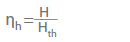
See Fig. 4 Shaft seal
As the leakage with gland packings is relatively high compared with mechanical seals, the former are mostly employed for environmentally friendly fluids only.
The gland packing can be operated without cooling for fluid temperatures up to 120 °C.
When used with hot water up to 180 °C, the gland packing must be fitted with a cooling jacket. For higher temperatures cooling is ensured via a combination of an internally cooled shaft protecting sleeve and a cooling jacket.
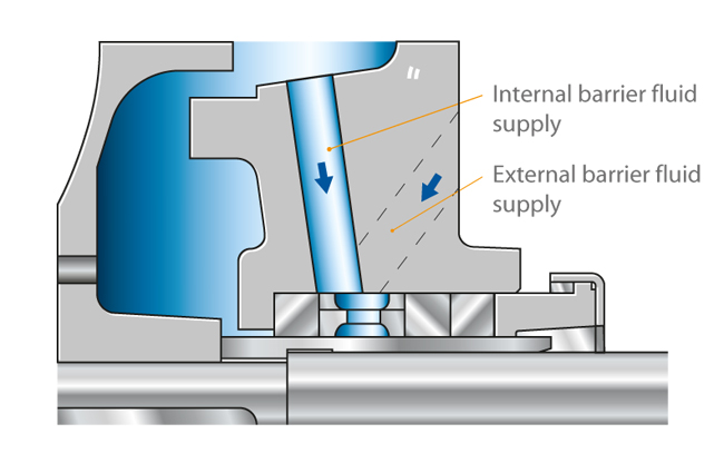
If the pump is used in suction lift operation, a barrier fluid line and a lantern ring fitted after the first packing ring ensure that air cannot enter via the packing. Provided the pump handles a clean fluid, this barrier fluid is supplied via the pump's
discharge nozzle or via an internal bore.
See Fig. 5 Shaft sealAs the pump discharge pressure is higher than the atmospheric pressure, air cannot penetrate the pump.
The barrier fluid pressure should normally be approx. 10 % or at least 2 bar higher than the highest pressure to be sealed.
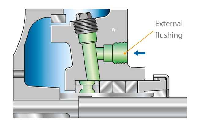
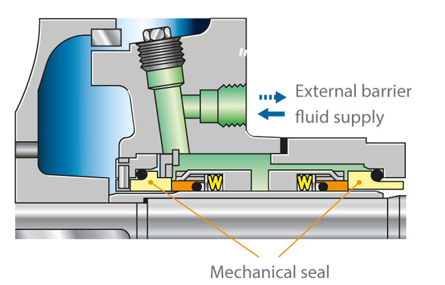
A barrier fluid connection is also required under suction head conditions (positive pressure), if the fluid is contaminated. If this were not the case, the contaminants would be forced through the packing with the leaking fluid. The contaminants would settle at the contact face of the gland packing and rapidly destroy the shaft protecting sleeve due to their abrasive effect.
In this case, an external barrier fluid supply is the only suitable option. The lantern ring would then be fitted as the innermost ring.
See Fig. 6 Shaft seal
As the barrier fluid pressure is higher than the pump pressure, a certain amount of the barrier fluid mixes with the fluid handled inside the pump, so that compatibility between the barrier fluid and the fluid handled should be ensured.
When the gland packing is serviced, both the packing cord and shaft protecting sleeve must be assessed for wear. If the shaft protecting sleeve has a hard, wear-resistant surface, this generally has a positive effect on the gland packing’s service life. Chrome plating, surface nitriding or plasma coating are excellent methods for hardening shaft protecting sleeves at the area subject to packing ring abrasion. Surface hardness should be higher than 800-1000 HV (Vickers hardness).
This method is particularly important when the fluid's purity cannot be guaranteed at all times. As this hard coating is very thin, shaft protecting sleeves which have undergone such treatment cannot be remachined during servicing.
Mechanical seal
Unlike gland packings, mechanical seals have a sealing gap which is positioned at a right angle to the shaft axis. These shaft seal designs are also called axial or hydrodynamic mechanical seals. Compared with gland packings, they require less space and no maintenance.
Mechanical seals are well-suited for sealing low and high pressures and circumferential speeds. The risk of inappropriate operation is therefore very low.
However, considerable disadvantages arise through wear caused by abrasive fluids (see
Abrasion). As is the case with gland packings, clean barrier or flushing fluids (e.g. cleaned by means of cyclone separators) help to keep abrasive particles away from vulnerable seal faces.
Pressed together by hydraulic and mechanical
forces, two seal faces slide relative to each other during operation. The sealing gap lies between these precisely machined seal faces and is filled with a lubricating film, generally a liquid. The sealing gap width (i.e. the distance between both seal faces) is influenced by various factors, including the seal faces' surface quality (i.e. how rough or smooth they are) and the sliding velocity.
Leakage from mechanical seals is very low; the fluid leaks into the atmosphere in the form of vapour or droplets. To calculate the mechanical seal's leakage rate, a gap width of under 1 μm is normally assumed. Thanks to this extremely narrow gap, the leakage rate for mechanical seals is considerably lower than that for shaft seals with radial gaps.
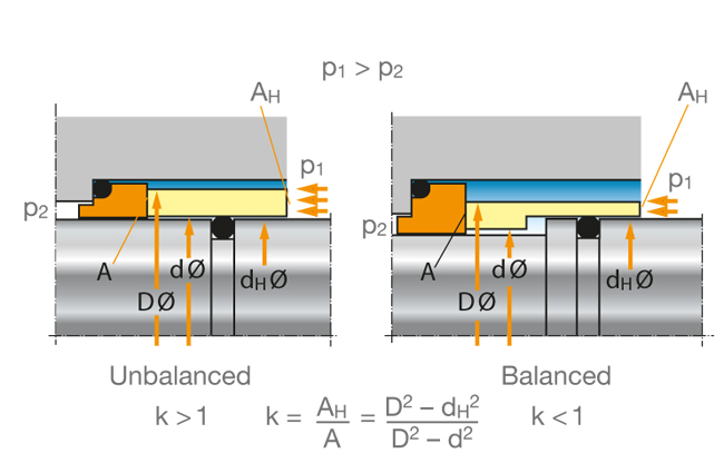
A further important differentiating feature is that seals can be unbalanced and balanced. In the case of unbalanced mechanical seals, the seal face is exposed to the complete pressure to be sealed.
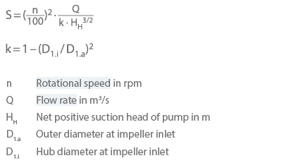
In the case of balanced seal types, a shoulder on the shaft or shaft sleeve ensures that only a portion of the fluid pressure is active as an
axial force.The load factor (k) characterises and defines the ratio of the hydraulically unbalanced area (AH) and the seal face area (A).
See Fig. 7 Shaft seal
If the k value becomes smaller, the seal face loads are reduced. For this reason, only balanced mechanical seals are employed in high-pressure and high-velocity applications.
A low k value results in both an improved lubricating film and a higher leakage rate. However, an excessively low k value may in extreme cases cause the complete separation of the seal faces resulting in a loss of the sealing effect.
Alongside the hydraulic closing force, spring forces provide an additional axial force acting on the sealing gap. The springs can employ an open or enclosed design and be in contact with the fluid handled or not; they may or may not transmit torque.
Spring types employed
- Central spring, conical or cylindrical, mounted onto shaft as single spring
- Multi-spring arrangement consisting of concentrically arranged multiple springs
- Metal bellows
- Wave springs
The friction losses generated are lower than those of gland packings. Heat is generated in the shaft seal housing due to friction; depending on the amount produced, it can be dissipated either via convection from the seal housing to the atmosphere or via forced circulation through an externally installed heat exchanger.
As with gland packings, mechanical seals are available in various designs and configurations to handle diverse operating conditions.
Frequently used designs
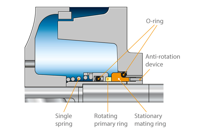
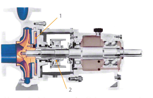
- Single, unbalanced mechanical seal as a typical example for a centrally arranged, conical single spring: The variant shown here is for "dead end" installation, i.e. there is no additional fluid circulation in the mechanical seal area.
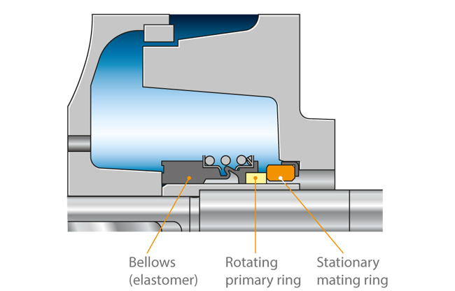
See Fig. 8 Shaft seal - Unbalanced mechanical seals are used for pressures of up to max. 15 bar and sliding velocities of up to max. 15 m/s. In general, a sufficient proportion of friction heat generated in the sealing gap can be transferred to the fluid handled and dissipated from the shaft seal housing to the atmosphere via convection. If the fluid handled is cold, the friction heat is absorbed by the fluid itself. One variant is the rubber bellows seal (bellows-type mechanical seal).
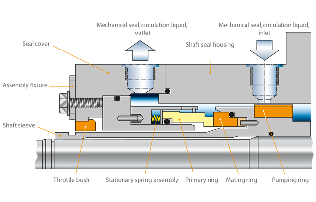
See Fig. 9 Shaft seal - Unbalanced mechanical seal with stationary spring assembly: this design is used for higher sliding velocities and ensures the springs can reliably fulfil their task (rotary spring assembly would entail a risk of broken springs due to high centrifugal forces).
See Fig. 10 Shaft seal
Varying spring arrangements are just one example of the distinctive features represented in the wide range of mechanical seal designs tailored for various
operating conditions.
Mechanical seal arrangements
- Single seal arrangement
See Figs. 8, 9 and 10 Shaft seal - Multiple seal arrangement
See Fig. 11 Shaft seal
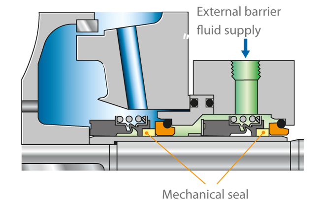
In the case of "back-to-back" arrangements, a barrier fluid is fed into the space between the two mechanical seals. Its pressure should be approx. 10 %, and at least 2-3 bar, higher than the pressure of the fluid handled by the pump.
See Fig. 11 Shaft seal
This barrier fluid ensures that the fluid handled does not leak into the atmosphere. Before considering this arrangement, it should be established whether a zero-leakage pump such as a
canned motor or
mag-drive pump would be more suitable for the application.
As the barrier fluid absorbs the friction heat generated by the two mechanical seals, it must be circulated, i.e. removed from the seal cavity, cooled and returned to the seals.
The barrier fluid pressure is generated by a barrier fluid system (thermosyphon vessel) or pressure booster. In the case of tandem seals, the space between the seals is flushed by unpressurised quench liquid (
quench). If the leaking fluid handled by the pump has a tendency to crystallise when in contact with air, a seal arrangement comprising two rubber bellows seals should be used. It is important that the quench liquid and fluid handled are compatible.
See Fig. 12 Shaft sealInstead of using an outboard mechanical seal, it is also possible to install a simple sealing element such as a lip seal or packing ring. It is fitted as a back-up seal for the main seal to prevent leakage (e.g. in the case of hazardous
fluids) and to safely and reliably dissipate
heat.
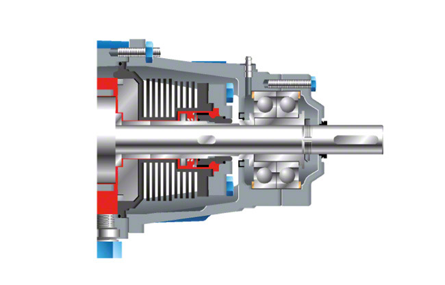
Tandem seals are employed when a high internal pump pressure requires distribution to two mechanical seals. The barrier fluid pressure level then lies between the pressure to be sealed and the atmospheric pressure. The pressure handled by the inboard seal corresponds to the difference between the pressure to be sealed and the barrier fluid pressure; the pressure handled by the outboard seal corresponds to the difference between the barrier fluid pressure and the atmospheric pressure. The barrier fluid must circulate in order to dissipate the friction heat generated by the seals.
See Fig. 13 Shaft seal
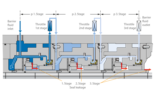
These mechanical seal types are used in the boiling or pressurised water reactors of nuclear power stations and are installed in main coolant pumps to seal extremely high pressures.
A three-stage seal arrangement is employed to seal a pressure of 160 bar in a pressurised water reactor, for example.
The pressure must be distributed via an auxiliary system, e.g. a three-stage cascading system of throttles arranged in the seals' bypass lines. A defined amount of water flows via the bypass line. Pressure is thus reduced by approx. 33 % at each throttle. The reduced pressure at each stage's output is the operating pressure for the next stage's input. This throttling and recirculation of the barrier fluid ensures the pressure is reduced and the friction heat removed from the sealing stages.
In the case of boiler feed pumps, seals have to cope with high sliding velocities, heat transfer from the fluid handled and the heat generated by friction.
See Fig. 14 Shaft seal
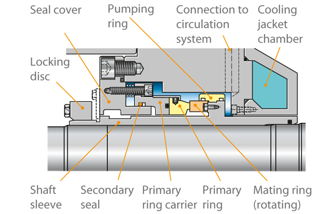
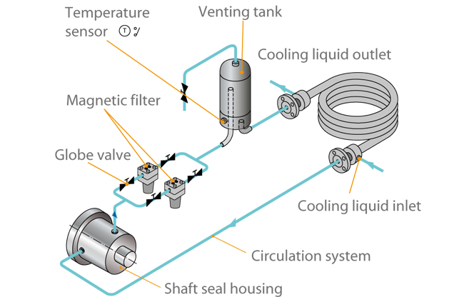
The sealing gap temperature is generally higher than the fluid temperature in the seal housing. The latter can be kept well below 100 °C by circulating the fluid through to an external cooler by means of suitable pumping devices inside the pump. Pumping screws, holes in the shaft protecting sleeve or small pumping discs serve as pumping devices.
See Fig. 15 Shaft seal
Magnetic filters ensure that the circulated water is absolutely clean. With high-specific speed pumps,a venting tank is essential to reliably remove any air from the circulation liquid.
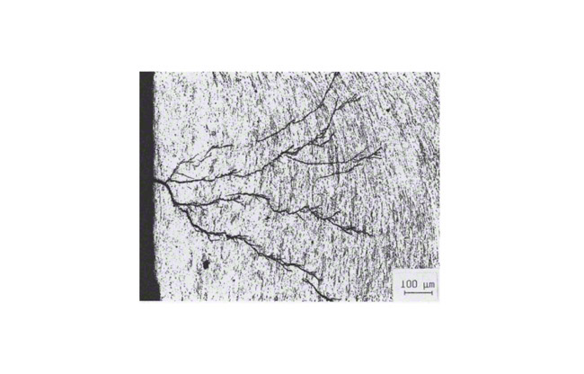
Detrimental
dry running of the mechanical seal may occur if the pump is operated without liquid fill and in the event of a major ingress of gas, a high
gas content or the evaporation of the fluid handled. Due to its low density, the gas always tends to move to smaller diameters which is the sealing gap of seals in most cases. The presence of air in this space leads to dry running and also impedes sufficient heat dissipation from the sealing gap resulting in thermal overload of the seal faces and mechanical seal failure (heat stress cracks) within a very short time.
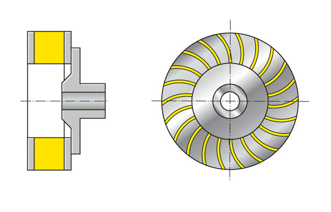
External cooling circuits are not used if the heat losses generated by the seal can be dissipated to the atmosphere via free convection and heat radiation.
See Fig. 16 Shaft seal
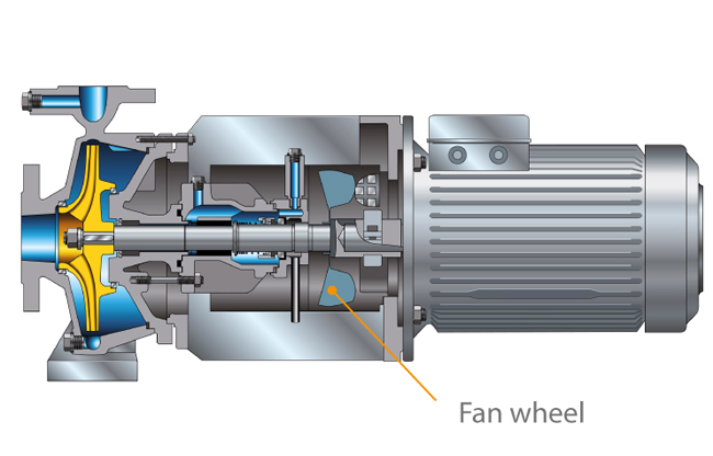
Other forms of cooling comprise a fan impeller mounted to the pump shaft to intensify convection (forced convection). In both cases the seal housing is provided with fins, at a right angle to the shaft axis (without fan impeller) see Fig. 16 Shaft Seal, and parallel to the shaft axis (with fan impeller).
See Fig. 17 Shaft seal
In the case of uncooled mechanical seals operated at high temperatures, the temperature in the sealing gap is generally higher than the temperatures in the sealing gaps described so far. This means that the boundary between the liquid and vapour phase in the sealing gap inevitably shifts towards the sealing gap inlet, increasing the risk of insufficient lubrication.
Non-contact seal with radial gap
This category encompasses all throttling gaps with or without labyrinths, pumping rings/screws and floating ring seals.
The sealing gap width between the stationary component and the rotating component is designed to be as narrow as possible in order to minimise leakage. However, it is important to ensure that the parts do no rub against each other. Leakage on a rotating shaft is slightly lower than during standstill.
The fluid flowing through the gap allows the pressure to be reduced in relation to the atmospheric pressure. On throttling gaps and floating ring seals this is achieved in the gap due to fluid friction and due to flow losses when the fluid enters or leaves the gap.
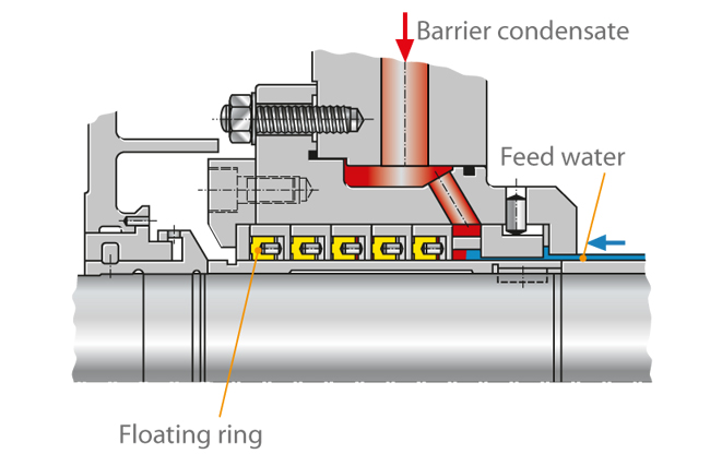
Floating ring seal
- The major advantage of floating ring seals is the fact that the components are not in contact. However, the time and costs required to provide the barrier condensate, its treatment and relevant control equipment are substantial.
- Thanks to their non-contact nature, these seals can be used for high circumferential speeds and mid-level pressures (30 to 50 bar).
See Fig. 18 Shaft seal
- With regard to their reliability, they are almost independent of the feed water's chemical composition.
- The floating ring seal consists of several short throttling rings fitted in succession which can move in a radial direction and centre themselves automatically due to the pressure distribution on the ring. A cold barrier condensate injected into the seal ensures that hot water from the pump does not escape to the atmosphere (controlled system). As long as the pump is in operation or under pressure, barrier water supply must be ensured.
- The floating ring seal is occasionally employed in boiler feed pumps. Its barrier condensate quantity can be controlled via the barrier condensate's pressure and temperature difference.
See Fig. 19 Shaft seal
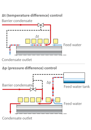
- For differential temperature control
- (Δt control), the difference between the temperature of the barrier condensate at the outlet and that of the injection condensate is defined. In the case of boiler feed pumps, the amount of feed water escaping from the inside of the pump is very low, while penetration of cold water into the pump can be ruled out.
- For differential pressure control (Δp control), the difference between the injection pressure and the inlet pressure is defined. A very small amount of barrier condensate flows into the pump. This puts high demands on the cleanliness and gas-free condition of the barrier condensate required to prevent the main circuit from being contaminated.
Instead of a floating ring seal, a labyrinth seal can also be used.
Labyrinth seal
- The labyrinth seal is a firm throttling bush with a circular groove profile. As radial movement is impossible with this type of seal, the diametral clearance must be wider than that employed with floating ring types. As a consequence, the leakage rate is higher, in turn requiring a higher barrier water flow rate.
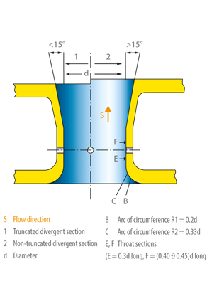
Centrifugal seal
- This type of shaft seal generates pressure itself in order to counteract the differential pressure to be sealed; it is frequently backed up by a standstill seal. Designed as spring-loaded mechanical seal, it is opened by centrifugal forces at very low speeds and thus protected against wear. See Fig. 20 Shaft seal
- The actual centrifugal seal (fitted as an auxiliary impeller using a liquid ring at the outer diameter) operates contact- and wear-free.
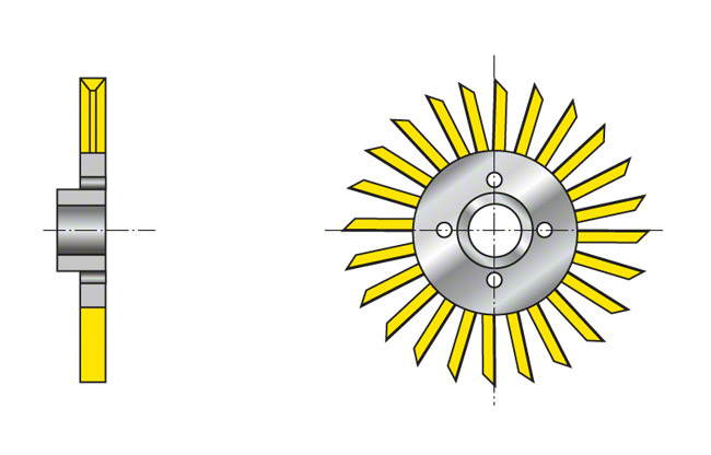
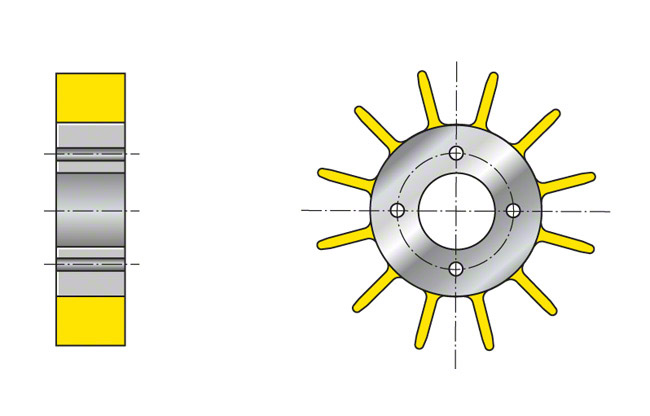
Pumping ring/screw
- Optimally designed pumping rings/screws (thread pitch of the stationary part directed against the pitch of the rotating part) can also generate a back pressure capable of balancing the pump's internal pressure when the pump is running. The pressure balance achieved this way depends on the rotational speed, thread length, gap width and mean gap diameter.
- Heads of 10 to 30 m can be achieved.
- As soon as the shaft stands still, however, the pumping ring/screw has only a throttling effect comparable with a labyrinth gap.
- If a pumping ring/screw is to serve as a pump seal, it needs to be backed up by a contact-type standstill seal.
See Fig. 21 Shaft seal
Hydrostatic seal
- Due its design, proper functioning of the hydrostatic seal as a non-contact seal is only ensured at pressures from 20 bar. The pump drive must not be started until this pressure level is reached.
- As the seal is very sensitive to solid particles, the barrier water which feeds the seal must be extremely clean.
- The sealing gap is self-adjusting. Depending on gap geometry and the pressure to be sealed, the sealing gap will adjust itself at about 10 μm.
- The gap's stiffness is very high at full operating pressure (160 bar). To move the gap from its balanced position by 1 μm, an external force of approx. 4000 N would be necessary.
- The gap with which the seal operates may be very narrow, but it is finite, and as such exhibits a considerable leakage rate (p = 160 bar, n = 1.500 rpm; sealing diameter at 260 mm, Q = 800 l/h). It is therefore necessary to back up the hydrostatic seal with a low-pressure seal that provides sealing to atmosphere.
See Fig. 22 Shaft seal
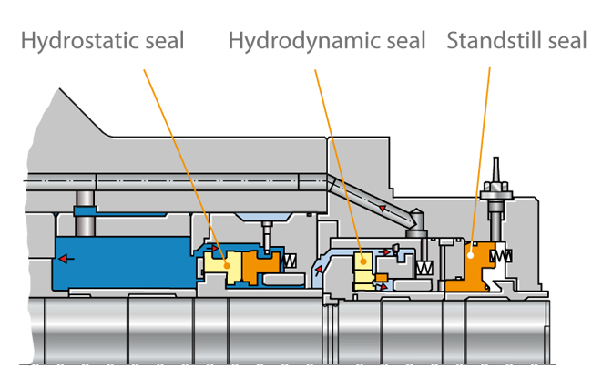
- Due to the hydrostatic seals’ operating limitation at low pressures, they have been replaced with hydrodynamic mechanical seals in many nuclear power stations.
- They are only used in main coolant pumps of pressurised water reactors.
Static contact seal
Static contact seals include O-rings. These are moulded seals and are defined as "rings with circular cross section made of elastic materials; they seal through the effect of slight bracing during installation, intensified by the operating pressure" according to DIN 3750. Their symmetrical cross-section rules out incorrect installation.
As connecting components can be easily calculated and designed, their use is widespread.
O-rings are employed on all the shaft seals described here. However, they can only be used as static sealing elements or to seal areas where slight axial movement is occasionally required.
They are manufactured at different hardness degrees, specified as shore hardness (A or D). The hardness scale ranges from 0 to 100, 0 being the lowest and 100 the highest hardness unit.
The majority of O-rings used on mechanical seals are
elastomer rings with a shore A hardness of 70 to 90. These O-rings are used for sealing between the shaft sleeves and the shaft, and between the primary ring or the mating ring and the respective components they are connected with. They ensure that the spring-loaded seal component can follow small axial shaft movements.
Their significance is often underestimated: ultimately, each shaft seal is only as good as its O-ring. O-rings must be matched to the fluid handled, cover a defined temperature range and provide good ageing resistance. Moreover, it is important to use a high-quality O-ring grease which meets the operating requirements. Besides providing long-term lubrication, the grease must be compatible with the fluid handled and must not attack the O-ring.
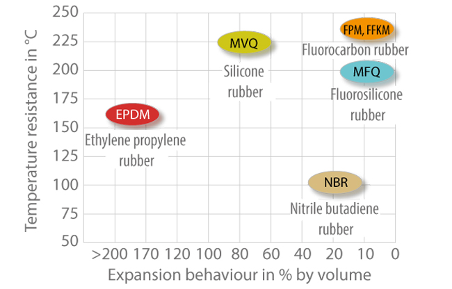
Elastomers which swell less than 10 % in the operating fluid and do not chemically react with the fluid handled are suitable for use as a mechanical seal's secondary seal. A number of elastomers are available for this purpose which react differently in a reference oil with regard to temperature resistance or swelling properties.
See Fig. 23 Shaft seal
Particularly critical are applications in chemical plants and refineries where pumps are frequently employed to handle different types of fluids.