Radial thrust
Radial thrust in centrifugal pump engineering is a hydraulic radial force in the plane of the impeller, generated by the interaction between the impeller and the pump casing or the diffuser.
Steady radial force
The steady hydraulic radial force (R) in volute casing pumps is generated by the interaction between the impeller and the casing. Its vector changes its magnitude and direction with the Q/Qopt ratio (q), i.e. the quotient between the flow rate (Q) and the flow rate (Q) at best efficiency point (Qopt).
The magnitude increases with the density (ρ), the projected impeller outlet area (B · D) and the head (H) where q is constant, and the direction (φ) remains unchanged. See Fig. 1 Radial thrust
The magnitude increases with the density (ρ), the projected impeller outlet area (B · D) and the head (H) where q is constant, and the direction (φ) remains unchanged. See Fig. 1 Radial thrust

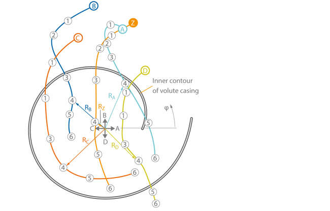
Fig. 1 Radial thrust: Radial force vector (R) curves for centred and eccentric impeller positions in a centrifugal pump's volute casing with ns = 26 rpm. The parameters are: Z Start of the force vector curve with q = 0 for the centred impeller position A , B , C , D Start of the force vector curves with q = 0 and an eccentricity of 2 % of the impeller radius in the direction of A, B, C and D (see intersection of axes)
1 q = 0.25
2 q = 0.5
3 q = 0.75
4 q = 1.0
5 q = 1.25
6 q = 1.5
Radial thrust is defined as:
R = K · ρ · g · H · D · B
R Radial force
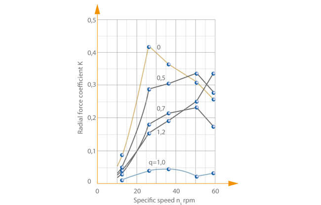
K Radial force coefficient See Fig. 2 Radial thrust
ρ Density of the fluid handled
g Acceleration due to gravity
H Head
D Outside diameter of impeller
B Impeller outlet width
R Radial force
K Radial force coefficient See Fig. 2 Radial thrust
ρ Density of the fluid handled
g Acceleration due to gravity
H Head
D Outside diameter of impeller
B Impeller outlet width
If the radial force (R) is plotted against the Q/Qopt ratio (q), a minimum results for volute casing pumps at the design point (q = 1) whereas the radial force increases rapidly in the low-flow range (q < 1) and the overlaod range (q > 1) (see Operating behaviour). The radial force (R) magnitude depends heavily on the specific speed (ns).
However, if the impeller is positioned eccentrically in the base circle of the volute, notable de-centring forces also occur at the design point while the radial forces may be smaller at other duty points. Fig. 1 Radial thrust shows an example of a volute casing pump with a specific speed of ns = 26 rpm and its force vector curves, where radial force vectors for six different Q/Qopt ratios (q) radiate from the centre (incl. the connecting lines between end points). It also shows the vectors for one centred and four eccentric impeller positions in the pump casing (the direction of point A points to the volute's tongue).
Vectors RA, B, C, D for the best efficiency points (at q = 1) are included on all five force vector curves as an example. At BEP the centred rotor position (curve Z) results in the smallest radial forces. The force minimum of the remaining force vector curves for eccentric impeller positions is larger and also lies outside of the best efficiency point.
In theory, radial forces do not occur with pumps fitted with diffusers because of the symmetrical flow around the impeller's circumference. However, in reality radial forces do occur as a result of inaccuracies in the manufacturing process. The max. value of this radial force can be estimated by applying a radial force coefficient of (K = 0.09). This value applies irrespective of the pump's Q/Qopt ratio (q). The radial force's direction on pumps fitted with diffusers is arbitrary. See Fig. 2 Radial thrust

Fig. 2 Radial thrust: Magnitude of the radial force coefficient K for a volute casing pump as a function of the specific speed ns and the Q/Qopt ratio q
The forces acting on impellers fitted in annular casings are lowest in the low-flow range and continually rise towards the overload range. Double volute casings are frequently used (see Pump casing) in order to reduce the forces. See Fig. 6 Volute casing pump
Unsteady radial force
Unsteady and in some cases rotating radial forces may be superimposed onto the steady radial forces. They may have different causes and characteristics. The best-known are the unsteady hydraulic radial forces with a frequency = number of impeller vanes x rotational speed. These radial forces appear to a greater or lesser extent in all types of pumps.
In particular in diffuser-type pumps (see Diffuser) rotating hydraulic radial forces develop under low flow conditions and when the rotor is in centred position (rotating frequency approx. 1/10th of the pump speed).
