Energy recovery
Energy recovery describes the process of recovering the Energy which has been used for the completion of a given task and of re-using it in the same or another process (e.g. centrifugal pumps used as turbines or pressure exchangers in reverse osmosis seawater desalination applications).
See Fig. 1 Energy recovery
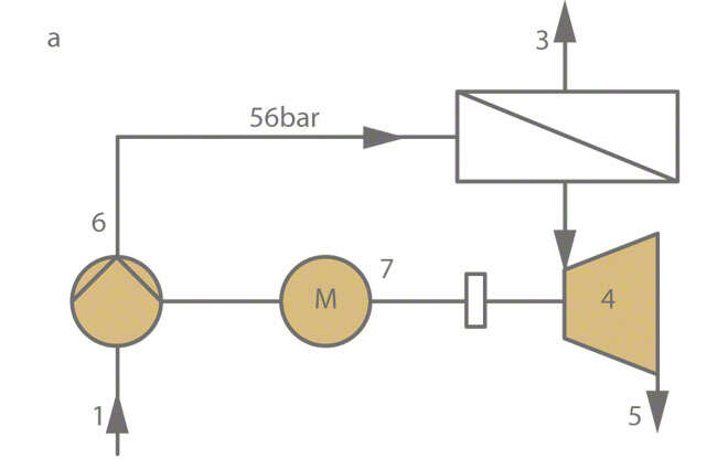
Fig. 1 Energy recovery: Example of energy recovery in process engineering (reverse osmosis); see also Specific energy 1 Seawater; 2 Membrane; 3 Drinking water; 4 Recovery system (turbine); 5 Brine; 6 Pump; 7 Electric motor; 8 Coupling
Energy recovery can be achieved with a minimum of investment costs (life cycle costs) if the recovery system's output torque can be directly recovered, i.e. without the installation of control equipment being required. This applies to all configurations where a three-phase motor is operated in the proximity of a recovery system whose power rating is higher than the power recovered from the system. A further cost reduction can be achieved if this motor and the recovery system are operated simultaneously. In this case it is sufficient to connect the recovery system's shaft to the electric motor.
The torque transferred this way reduces the power input required by the electric motor. In addition, the motor determines the recovery system's rotational speed. This means that in the event of fluctuations in the energy recovery system's output rate due to changes in the hydraulic operating conditions, the speed remains almost constant and the torque transferred is the only parameter that will be affected.
If certain minimum values for flow rate and head are not maintained, the torque may become negative so that it has a retarding effect. This can be avoided by providing a free-wheel clutch between the recovery system and the generator.
Directly exploiting the torque delivered by the recovery system represents the simplest, and as such the most efficient, utilisation of the energy recovered. If the recovery system is combined with a pump and both units are fitted to the same shaft assembly, the pump rotor and the turbine wheel should be accommodated in the same casing as long as they are compatible with the fluid's physical and chemical properties. See Fig. 2 Energy recovery
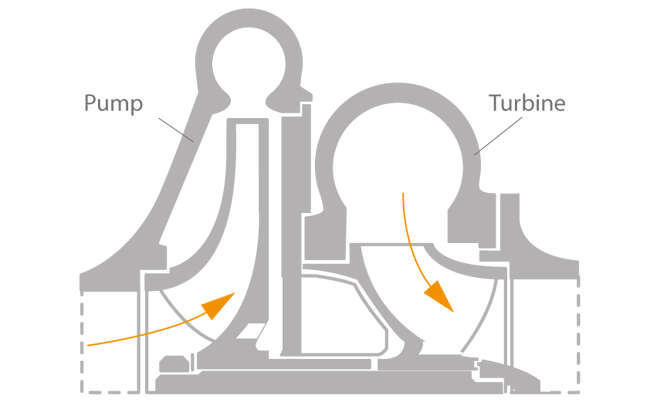
Fig. 2 Energy recovery: Energy recovery using an energy converter
The example of a drinking water system demonstrates how and when energy recovery is possible. Such systems are generally designed to provide the consumer with a suction head (H) of 50 m (5 bar) at the tapping point. In this case each cubic metre of water tapped contains a technical power potential (W) of 0.136 kWh:
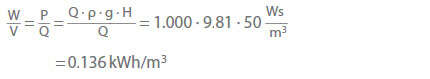
P Power loss due to throttling in W
Q Flow rate of the water tapped in m3/s
V Water volume in m3 as reference basis
W Technical power potential in kWh
Exploiting energy available at such a low level of concentration is not worthwhile. If, however, the drinking water system's main pipes handle large flow rates and the pressures in the piping exceed the pressure at the consumer (5 bar) several times over, then the level of concentrated power losses at the throttling points is much higher. These losses represent potential recoverable energy which can still be exploited in an economically efficient manner, down to power ratings of 20 kW.
A further example of possible energy recovery is the routing of pipelines across uneven terrain, especially in hilly regions. This requires the installation of pressure reducing stations. See Fig. 3 Energy recovery
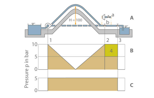
Fig. 3 Energy recovery: Potentially recoverable throttling energy of a main drinking water pipe laid with a rising and downward slope A Topographic longitudinal section of an installation B Static pressure profile of the rising and downward pipe C Static pressure profile of the horizontal pipe (friction and velocity energy not taken into account) 1 Pumping station; 2 Pressure reducing station (see Fig. 4 Energy recovery) (a: Turbine with gate valve, b: Throttling valve); 3 Consumer; 4 Pressure energy recovered in turbine operation (∆p = 5 bar)
When pipes are laid at rising and falling gradients, the pressure must be increased in a pumping station upstream of the hill, and reduced downstream of the hill. Otherwise, a negative pressure would develop at the highest point of the pipe resulting in the separation of the water column.
When the main pipe is routed via mountain ranges and the target station is located at a lower level or at the same level as the pumping station, the potential for recoverable energy is high. The target can be a pressure reducing station used for pressure regulation (see Fig. 4 Energy recovery), or the intake of a reservoir where the full pressure is reduced to zero by means of the inlet throttling device. The flow rate is thus regulated by the throttling element.

Fig. 4 Energy recovery: Pressure control station with a pump used as turbine installed in the bypass line 1 Control valve l; 2 Pressure gauge; 3 Tachometer generator; 4 Pump used as turbine; 5 Control valve II; 6 Generator; 7 Disc brake; L1, L2, L3 = Electrical grid
