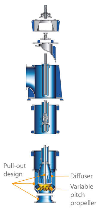
Tubular casing pump
A tubular casing pump is a centrifugal pump, in which the fluid handled, having passed the impeller and the diffuser, flows through the tube shaped pump casing (in the case of vertical tubular casing pumps, the column pipe is concentric with the pump shaft. The most common tubular casing pumps are vertical pumps.
In the case of a wet well installation, the pump's bellmouth is submerged in an intake chamber which is either open at the top or covered; dry-installed tubular casing pumps are bolted onto an intake elbow at their suction end, or are connected in a leak-tight manner to the cover of an intake chamber.
In all cases, it is important that the inlet conditions of tubular casing pumps are carefully studied. The tubular casing and discharge elbow can be made of concrete for reasons of economy. See Fig. 7 Cooling water pump
The impeller is either an axial impeller or mixed flow impeller depending on the specific speed. The diffuser leads into the column pipe and, depending on the installation depth, several lengths of column pipes can be bolted together in succession. As a result, the pump shaft needs to be longer and it must be supported by several bearings. The discharge elbow at the end of the column pipe guides the flow towards the end of the pump discharge nozzle.
The shaft exits the tubular casing at the level of the discharge elbow and is sealed by a gland packing or a mechanical seal. The motor stool arranged above accommodates the thrust bearing (plain bearing, rolling element bearing) and provides access to the shaft coupling between pump and drive or gear unit (e.g. spur gear).
The drive for pump control is also accommodated in the motor stool. The impeller blade pitch adjustment of the propeller pumps is predominantly actuated through the hollow drive shaft. Pre-swirl control of mixed flow pumps is usually actuated from here via special universal joint shafts.
The shaft guide bearings are maintenance-free, water-lubricated ceramic plain bearings. These bearings do not require clean fresh water or a filtered portion of the fluid handled for lubrication, and they can cope with handling heavily contaminated, unfiltered fluids.
As the installation and removal of the tubular casing is rather cumbersome due to the weight and bulky proportions of the items involved, tubular casing pumps in pull-out design allow the complete withdrawal of the hydraulic components such as impeller and diffuser including shaft and bearings (rotating assembly) from the tubular casing (see Pump in pull-out design).
See Fig. 1 Tubular casing pump
See Fig. 1 Tubular casing pump

Fig. 1 Tubular casing pump: With variable pitch propeller and pull-out rotating assembly including diffuser
For this purpose, the discharge elbow must be designed with an opening at the drive end whose diameter is equal to the tubular casing and which is sealed by a discharge cover. In this case an inspection or replacement of the rotating assembly only requires that the motor and motor stool are dismantled and that, after the discharge cover bolts have been undone, the complete rotating assembly is withdrawn. The discharge-side connection and the suction-side connection (if applicable) of the tubular casing remain undisturbed.
If several identical pumps are installed, a complete spare rotor (rotating assembly) can be kept on stock for replacement.
Especially when large nominal diameters are required, tubular casing pumps in pull-out design are the preferred choice. Their installation options are varied and are usually governed by the site conditions and characterised by the installation types the pump manufacturer can offer.
The pump impeller is continuously immersed in the fluid handled in order to eliminate the need for special suction devices or booster pumps. In the case of dry installation, the suction side of the pump must be connected to the intake elbow or to the cover of the intake chamber so as to be water- and air-tight.
All this amounts to additional capital investment costs which are, however, compensated by the advantages that the pump casing can be very short and that the pump is accessible for inspection from the outside at all times.
A tubular casing pump for wet well installation is submerged in the fluid handled at its inlet end. Thanks to its straightforward installation, a wet-well installed pump is employed much more often than a dry-installed tubular casing pump.
Another aspect to be determined for installation is the question of whether the tubular casing pump's discharge nozzle should be situated above or below floor level (the latter being the case with irrigation pumps). This decision should be made at the site.
Finally it must be decided how the weight of the drive is to be supported. The motor stool can be placed directly on the discharge elbow situated above floor level (provided the pump set does not become too "top-heavy" as a result), or the motor stool can be placed (cantilevered) over the discharge elbow without exerting any load on it (cantilevered motor stool), or the motor stool can be installed on a floor of its own at the engine room's next level up.
The rotating shafts and couplings must be equipped with appropriate contact guards. In certain rare cases – small nominal diameters and short overall lengths – the complete pump set can be installed on the intake chamber's floor by means of a special pump foot
Tubular casing pumps are primarily used as cooling water pumps, but they are also employed as pumps for low-lift pumping stations as well as booster pumps in seawater desalination systems.
