Marine pump
"Marine pump" is a collective term for all pumps complying with the relevant regulations issued by the shipbuilding classification societies.
Marine pumps designed as centrifugal pumps perform a great variety of duties on board (see Pump application): in the engine room as a boiler feed pump, condensate pump and cooling water pump using seawater or fresh water, in the bow as a transverse thruster in special pump rooms as a cargo oil pump, Butterworth pump or ballast pump, for special duties as an antirolling, antiheel or trimming pump, as a bilge pump, or stripping pump, as a fire-fighting pump and as a service pump for a variety of applications. Dock pumps are also classified as marine pumps. Cooling water pumps using either seawater or fresh water (e.g. seawater pump) and fire-fighting pumps draw in fluid from the sea chests via suction lines. Sea chests are tanks mounted to the inner side of the ship's hull below the water line. Their apertures face seawards and are covered by inlet screens.
If the fluid handled is seawater, suitable pump material is required: gunmetal or bronze (e.g. multi-alloy aluminium bronze) for the pump casing and impeller and chrome nickel steel for the pump shaft.
As bilge and ballast water lines often require large quantities of air to be evacuated, many of the pumps on board are self-priming pumps. They are water ring pumps which rotate continuously with the main pump. Separate bleeding devices (see Venting) such as ejectors or central vacuum systems are also gaining in popularity.
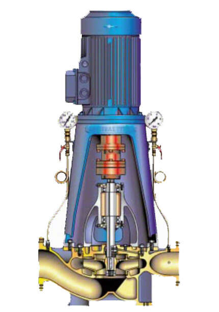
Due to the restricted installation space on board the most suitable design for the majority of marine pumps is a vertical pump in radially split) design with the motor mounted directly on top. See Fig. 1 Marine pump

Fig. 1 Marine pump: Radially split vertical marine pump in in-line design
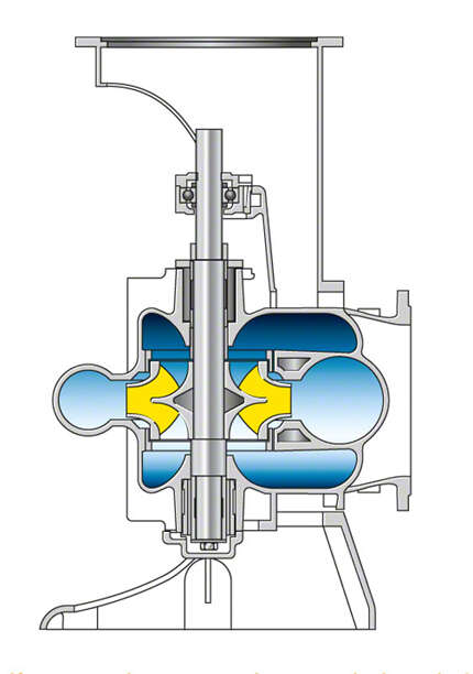
In some individual cases, axially split designs are used. See Fig. 2 Marine pump

Fig. 2 Marine pump: Axially split vertical marine pump
The flow rates of vertical, radially split marine pumps range from 30 to 1200 m3/h at heads of 15 to 125 m. Single-entry impellers are fitted for low flow rates and double-entry impellers (see Double-suction pump) for high flow rates. The pump shaft is guided in grease-packed rolling element bearings arranged outside the pump casing.
For inspection and repair purposes the rotating assembly can easily be lifted out upwards after removal of the coupling spacer sleeve (see Shaft coupling) The motor need not be removed, and the pump casing can remain installed on the pump foundation.
Axially split, vertical marine pumps are used for flow rates from 1,000 to 5,000 m3/h and heads of 15 to 85 m.
The pump shaft is guided in a grease-packed rolling element bearing below the shaft coupling and in a product-lubricated plain bearing below the impeller.
The front part of the casing has to be removed sideways before the pump rotor can be dismantled. See Fig. 2 Marine pump
On turbine ships equipped with large boiler plants and correspondingly large condensers, double-suction centrifugal pumps are used for cooling water supply. Because of the low heads involved, propeller pumps with an axially split casing are also sometimes adopted.
Marine condensate pumps have to able to operate at extremely low inlet heads. The first stage impeller (see Suction stage impeller) is a special impeller arranged at the bottom. The flow approaches it from underneath. To improve the NPSHR value inducers can be installed. The bearings are arranged outside of the fluid handled.
Marine condensate pumps generate flow rates ranging from 5 to 250 m3/h and heads of 30 to 140 m.