Three-phase current
Three-phase current can also be called three-phase alternating current or three-phase electric power and is used in the low-voltage network for end consumers (public power grid). The current carried here is limited to 400 volts in Germany and elsewhere.
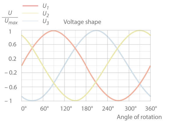
When three coils in a generator are arranged uniformly in circle, three corresponding (i.e. offset) alternating voltages are produced that reach their maximum amplitudes consecutively, at different times. These offset voltages are described by the phase angle.
With three-phase alternating current, phases are offset by 120 degrees. See Fig. 1 Three-phase current

Fig. 1 Three-phase current: Voltage shape, three-phase alternating current
The formula for calculating a single alternating voltage in a system carrying three-phase alternating current is:

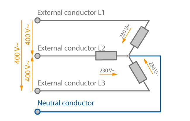
Power companies try to load the three phase conductors as uniformly as possible. When the three-phase alternating current system is branched into separate AC lines as found in households, symmetrical loading is no longer ensured. A neutral conductor (four-conductor system) is therefore added to carry the compensating currents as dictated by the degree of asymmetry between the external conductors. This neutral conductor, like the external conductors, is an "active conductor" of the three-phase system that can carry current in normal operation, as opposed to an additional earth conductor. See Fig. 2 Three-phase current

Fig. 2 Three-phase current: Three-phase system
Three-phase current can be used in a delta or star configuration.
Star configuration
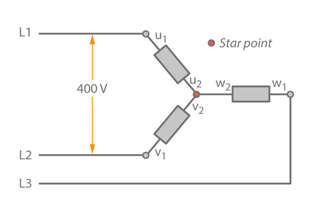
When a star configuration (three-phase system) is used, the three phase conductors in a three-phase system are interconnected at one end. The resulting convergence forms the centre point, or star point, which is connected to the neutral conductor (N). The free ends are then connected to the external conductors (L1, L2, and L3). See Fig. 3 Three-phase current

Fig. 3 Three-phase current: Star configuration
This arrangement is beneficial in that two different voltages can be tapped for a symmetrical load (i.e. the u, v, and w phases have the same impedance). Based on typical phase voltage in Germany, 230 V are carried between the external conductor (L1, L2, or L3) and the neutral conductor (N) . If the voltage between the two external conductors is tapped (e.g. L1 and L2), 400 V are obtained.
Combined use of the three phase conductors takes place in electric motors (three-phase motor) for example. When the voltages in a motor are routed by three coils arranged in circle, a rotating magnetic field is again produced and triggers rotation of a basic squirrel-cage rotor.
The ends of the three phase conductors are labelled as follows:

To operate an electric motor in a star configuration, external conductors L1, L2, and L3 are connected to conductor ends u1, v1, and w1:

The remaining ends of the phase conductors (u2, v2, and w2) are jumpered (interconnected) to realise the aforementioned star point.
Delta configuration
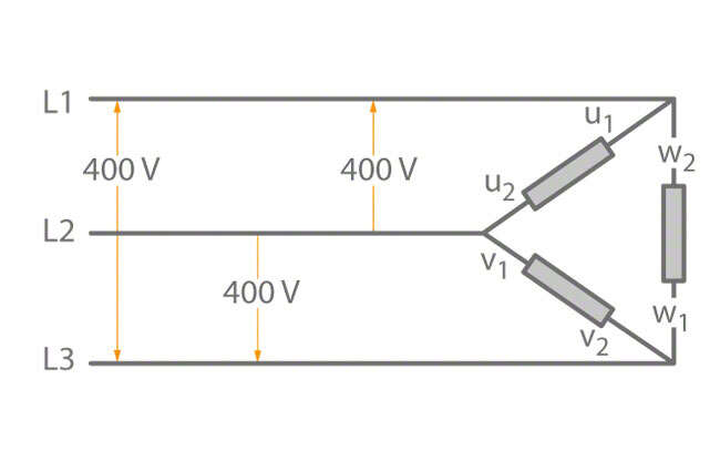
In a delta configuration (three-phase system), the three phase conductors of a three-phase system are connected in series, whereby the end of one phase conductor is connected to the opposite end of the next conductor. This gives rise to three intersecting points (u1, v1, and w1), to which the external conductors are connected and their designations are standardised: L1, L2, and L3 (before: R, S, and T).
See Fig. 2 Alternating current
A neutral conductor (N) is not required as for the star configuration. In consumer power networks in Germany and Central Europe, 400 volts are carried at the intersecting ends of the phase conductors, while the individual external conductors "earth" 230 volts. See Fig. 4 Three-phase current

Fig. 4 Three-phase current: Delta configuration
The delta configuration (three-conductor system) is normally used in industrial applications involving powerful machines and to carry electrical energy across large distances.
