Cooling water pump
Cooling water pumps are used for supplying heat exchangers with cooling water. Their flow rate varies depending on the heat flow to be dissipated. The required head is determined by the type of cooling system.
A distinction is made between wet cooling and dry cooling processes.
Range of head and flow rate
The required heads for fresh water operation usually lie within 5 to 15 m. In cooling tower operations they can be as high as 20 to 35 m.
The flow rate depends on the cooling process, the characteristics of the heat exchanger and on whether the pump is to be installed in a fossil-fuelled or a nuclear power station.
Reference values
- Cooling with fresh water (see Wet cooling):
fossil-fuelled power station 100-120 m3/MW
nuclear power station 140-160 m3/MW - Indirect cooling with air (see Dry cooling):
fossil-fuelled power station 80-100 m3/MW
nuclear power station 120-140 m3/MW
Impeller types
The required range of heads ranging from 5 to 35 m is covered by three types of impellers.
- Range of head per impeller type
- Up to 10 m axial propellers are generally used (specific speed ns > 150 rpm)
- From 10 to 25 m mixed flow propellers can be used (100 rpm < ns < 150 rpm)
- From 10 to 40 m diagonal impellers (mixed flow impellers) are used (70 rpm < ns < 150 rpm)
Naturally, all three types can also be installed in multistage pumps, which will extend the head range. However, a multistage design will always be more costly. It is only selected if such a type of pump is required to control the flow rate.
Type of pump
Cooling water pumps are usually vertical shaft tubular casing pumps or volute casing pumps which are made completely of metallic materials.
See Figs. 1 to 4 Cooling water pump
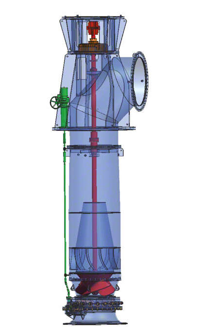
Fig. 1 Cooling water pump: Mixed flow pump with pre-swirl control equipment

Fig. 2 Cooling water pump: Tubular casing pump with (adjustable) mixed flow propeller
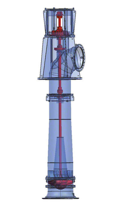
Fig. 3 Cooling water pump: Tubular casing pump with (adjustable) axial propeller
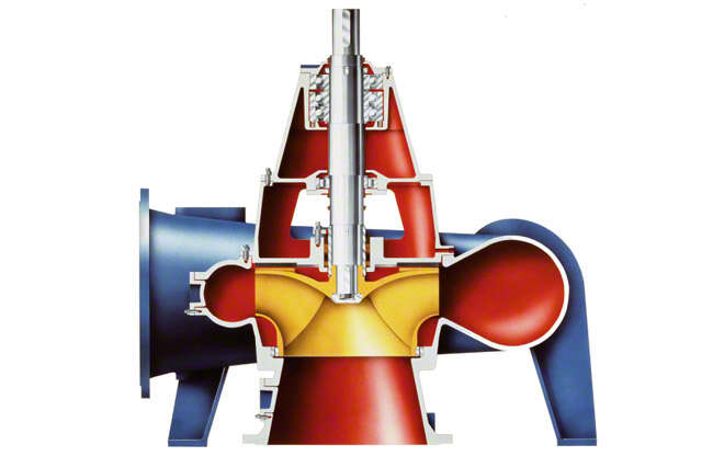
Fig. 4 Cooling water pump: Volute casing pump with mixed flow impeller
Less frequently, submersible motor pumps are also employed as cooling water pumps, e.g. with a mixed flow impeller (see Impeller). See Fig. 5 Cooling water pump
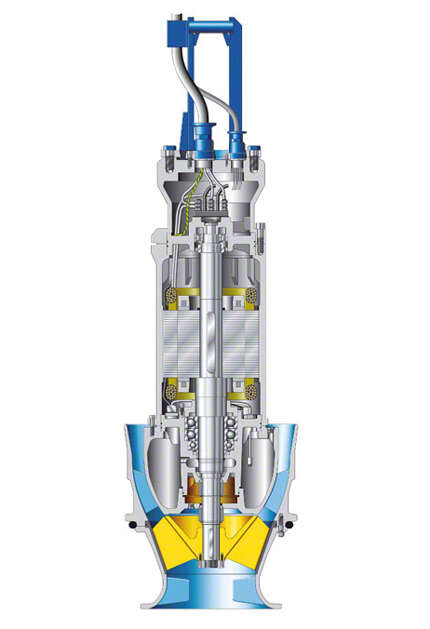
Fig. 5 Cooling water pump: Submersible motor pump with mixed flow impeller
For economic reasons, concrete casings are also chosen for volute casing pumps from DN 1200 to DN 1400 (see Nominal diameter) and for tubular casing pumps up to approximately DN 2000. In this case, the volute or tubular pump casings (see Pump casing) are partly or completely made of concrete. See Figs. 6, 7 Cooling water pump
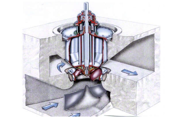
Fig. 6 Cooling water pump: Concrete volute casing pump with mixed flow impeller
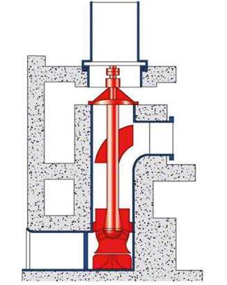
Fig. 7 Cooling water pump: Concrete tubular casing pump with adjustable mixed flow propeller (pull-out design)
The following impeller types are suitable for tubular casing pumps:
- Mixed flow impeller See Fig. 1 Cooling water pump
- Mixed flow propeller See Fig. 2 Cooling water pump
- Axial flow propeller See Fig. 3 Cooling water pump
Impeller types for volute casing pumps:
- Mixed flow propeller
- Mixed flow impeller, see Fig. 4 Cooling water pump
On board vessels (see Marine pumps) cooling water pumps with volute casings are also fitted with double-entry radial impellers (see Double-suction pump). See Fig. 8 Cooling water pump
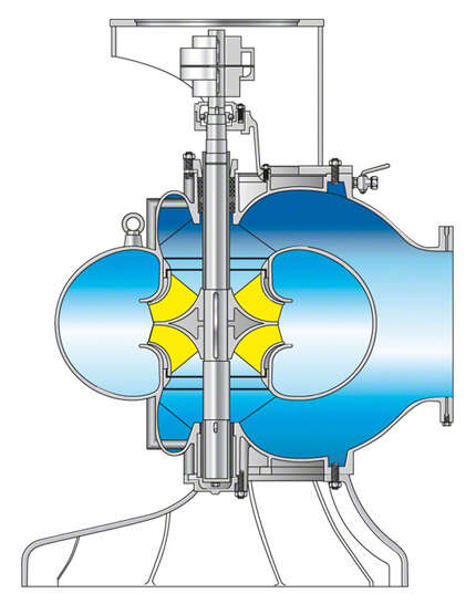
Fig. 8 Cooling water pump: Double-suction circular casing pump
Closed-loop control
In some cases a cooling water pump has to be controlled to react to changes occurring during the cooling process.
Reasons for controlling a cooling water pump:
- Adjusting the flow rate at constant head to the changing conditions in the heat exchanger (e.g. part load of the turbine)
- Adjusting the head at constant flow rate, if the pump head fluctuates with the water level on the suction side or if the operation changes over from fresh water to cooling tower operation
- If, after a pump failure, the remaining pumps are to pump 100 % of the cooling water flow
Cooling water pumps can be controlled in various ways:
Throttling
- Closing a throttling element (see Valve) in the discharge line (see Pump system) increases the head of the system and decreases the flow rate.
- There are limits to this type of control, as for specific speeds of ns > 100 rpm the pump power input increases with decreasing flow rate and may exceed the motor power available.
- In addition, the flow will separate from the vanes under specific low-flow conditions (see Operating behaviour) and the pumps will run rough (see Smooth running), which must definitely be avoided for continuous operation.
- Of the control methods described in this section, throttling generates the highest losses. Its use is generally confined to very small units. Throttling is not common in today's modern power stations.
Speed control
- Speed control is used for adjusting the rotational speed of the pump. As a result, the head, flow rate and pump input power are adjusted in accordance with the affinity laws. However, the greater the static component (HS,0) of the system head (HS) (see System characteristic curve) the more the operating point deviates from its optimum at reduced speed. In other words, it shifts toward low-flow operation and, hence, toward the cut-off point. See Fig. 4 Closed-loop control
- Speed is either controlled directly or via a speed modulation gearbox. Three-phase motors are frequently selected as drives. Direct current motors are generally not suitable due to the large amounts of pump input power required for cooling water pumps.
- Lately, motors with frequency inverter have increased in popularity, also for larger ratings.
- Thyristors are used for electric speed control of three-phase motors with large ratings.
Impeller blade pitch control
- This type of control is suitable for pumps with axial and mixed flow propellers. The impeller vanes are adjusted during pump operation.
- The characteristic curves selection chart of such pumps with all possible adjustment angles generally shows elliptically shaped efficiency curves with almost horizontal
principal axes. See Fig. 9 Cooling water pump - This is the optimum type of control in cases where large changes in flow rate at relatively small variations in head and an almost constant efficiency are required.
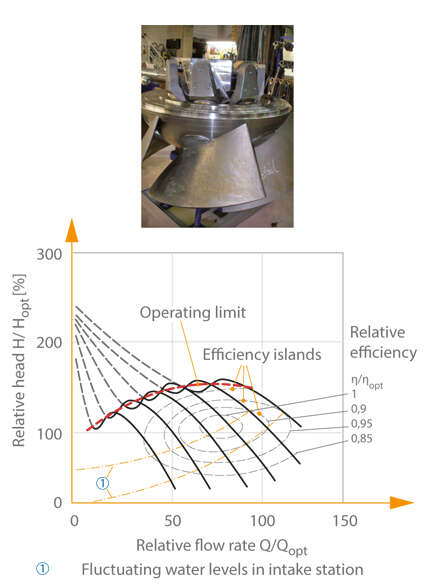
Fig. 9 Cooling water pump: Typical characteristic curves selection chart of a propeller pump controlled by axial or mixed flow impeller blade pitch adjustment (Top figure: Propeller head with blade pitch control equipment)
Pre-swirl control
- This type of control is used for pumps with mixed flow impeller. The flow upstream of the impeller is influenced by imparting pre-swirl. The flow rate is increased by inducing pre-swirl in the same direction as the impeller rotation or decreased by inducing pre-swirl in the opposite direction. This is effected by a stationary vane cascade with adjustable pitch angle, fitted upstream of the impeller. See Fig. 1 Cooling water pump
- The selection chart of such pumps with all possible pre-swirl angles generally shows elliptically shaped efficiency curves. The principal axes run (roughly) parallel to the pump characteristic curve. They differ in this respect from the ellipses of impeller blade pitch control, whose principal axes run almost horizontally. See Fig. 10 Cooling water pump
- This is the preferred type of control in cases where relatively small changes in flow rate at large variations in heads and optimum pump efficiencies are required.
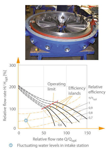
Fig. 10 Cooling water pump: Typical characteristic curves selection chart of a pre-swirl controlled mixed flow pump (Top figure: Pre-swirl control equipment for a cooling water pump)