C

Cable gland

A cable gland is used where the connection cable connects to the terminal box or the housing of the electric motor. It prevents moisture from reaching the terminal box. 

See Figs. 1, 2 Cable gland

This is an embedded image

This is an embedded image


Cable shield

A cable shield is the conductive sleeve of a cable or lead and protects the conductor inside from being exposed to external electromagnetic fields, while preventing electromagnetic radiation emanating from the signals carried by the conductor from escaping into the environment.

Cable shields are typically made from thin copper wire that is braided or stranded and can be enhanced with foil. They are protected by an insulating, corrosion-resistant, and water-tight jacket and are used for shielded cables.

CAN Bus

The term CAN is the abbreviation for Controller Area Network and denotes, in combination with the term "bus", a serial bus system. This systemis a field bus and connects sensors, control elements, drives and actuators with a control system (also see Communications system).

Canned motor

The canned motor is a special type of wet rotor motor, in which the stators winding is protected from the fluid handled by a cylindrical, particularly thin tube (e.g. made from stainless steel or plastic) inserted in the machine's "air gap" (in the gap between stator and rotor). The can must have low or negligible electrical conductivity to avoid insulation and corrosion problems in the stator winding.

Heat dissipation in the stator winding is complicated, however, because efficiency is reduced as a result of the eddy current losses in the can, the increase in the gap between the rotor and stator, and higher friction losses due to fluid friction at the rotor.

The power range of canned motors lies between several watts and approximately 2000 kW. Canned motors are employed wherever hot, aggressive, explosive, toxic or radioactive fluids need to be pumped, which is why a great deal of focus is placed on hermetically sealed pump sets without gland packings or mechanical seals. Canned motors are used for circulators reactor circulating pumps (see Reactor pump), and process pumps for chemical and process engineering applications.
See Fig. 1 Canned motor

This is an embedded image


Canned motor pump

The canned motor pump is a centrifugal pump, designated according to the nature of its drive. It is a sealless pump which is made of a highly corrosion-resistant material and is absolutely maintenance-free.
See Fig. 1 Canned motor

Permanently excited synchronous motors (see EC motor) are particularly efficient drives for canned motor pumps. The use of permanent magnets in the rotor allows losses (excitation losses) to be minimised. Leckage is contained in the flameproof enclosure of the motor.

Capacitive sensor

A capacitive sensor is a measuring instrument that utilises changes in the capacity of a capacitor for e.g. pressure or level measurement (also see sensor).

Carbonate hardness

Carbonate hardness is the main cause of water hardness. It is the term used to describe the hydrogen carbonates dissolved in water, which may, for example, be released by the dissolution of limestone.

Cargo oil pump

Cargo oil pumps are installed on board tankers. Their duty is to pump the oil out of the vessel's tanks into land-based tanks at the port of destination. This process is supported by the pumps' stripping system. In addition, cargo oil pumps are often used as ballast water pumps to adjust the vessel's draught.

Cargo oil pumps are installed in the pump room, which is usually located in the stern of the vessel, between the tanks and the engine room. The pumps are installed as low as possible.

At the beginning of the pumping process the inlet head is relatively large. When the oil level has sunk to a very low level, the suction lift can be up to 5 m or higher. At this stage of the pumping process, air ingress through the suction nozzles into the suction lines is a frequent occurrence, as the suction nozzles are no longer fully immersed in the fluid pumped. Special air removal equipment is used to remove the air before it enters the pump. 

Cargo oil pumps are driven by steam turbines, electric motors or Diesel engines. Their flow rate is adjusted by means of speed control (see Closed loop control). The connecting shaft between the engine room and the pump room is guided through a bulkhead with gland packing for safety reasons (fire and explosion protection).

The pump casings are usually double volute casings made of cast copper alloy material. See Fig. 6 Volute casing pump

Depending on the size of the vessel the pump's flow rate ranges from 1,500 to 9,000 m3/h; its head averages 150 m. Apart from submersible pumps, which can only be used for small flow rates, double-suction  pumps are generally employed because of their good suction capability at highest speeds. 

For both horizontal pumps and vertical pumps axially split designs of the pump casing with double-entry impellers are preferable.
See Fig. 1 Cargo oil pump

This is an embedded image

Vertical pumps can also be required in single-entry, single-stage radially split design.

The sturdy oil or grease-lubricated rolling element bearings are arranged in close proximity to the casing. Sealing is effected by means of mechanical sealsInducers are used if the NPSH values are low.

Carnot's shock loss

If the pipe diameter or flow cross-section suddenly widens from A1 to A2, the fluid does not enter the wider area as a constant jet with the velocity v1 but mixes with the surrounding fluid, accompanied by marked turbulence and vortex formation. At the end of a transition zone the fluid once again forms a uniform flow at a lower velocity v2. See Fig. 1 Carnot's shock loss

This is an embedded image

The pressure loss (Δp) due to mixing is called Carnot's shock loss and can be derived from the principle of conservation of momentum:

This is an embedded image

ρ    Density of the fluid handled


See Fig. 1 Fluid mechanics

Cavern pump

Cavern pumps are a special type of tank farm pumps. Caverns can take the form of salt deposits, old mines, depleted oil and gas fields, porous storages and blasted-out mine workings. Depending on the type of cavern, either above-ground, multistage high-pressure pumps or submersible borehole pumps of special design are used.

To ensure tightness of mine workings a water jacket is placed around the cavern. The pressure of the water must be somewhat higher than the vapour pressure of the stored medium. This enables oil caverns in depths of up to 60 m to be used; for storage of propane and butane, some 140 m.

Cavern systems are operated mainly using submersible motor pumps that are also known as submersible borehole pumps for use in tank farms.

They are equipped with submersible motors.

See Fig. 1 Cavern pump

This is an embedded image

The design of submersible motor pumps used for LPG caverns (propane and butane) does not provide for pressure equalisation diaphragms, as otherwise the LPG would diffuse into the motor space. The motors are therefore designed to be pressure-resistant up to 25 bar and subjected to static pressure from an above-ground water tank. LPG can even potentially diffuse into the connecting cables. Since cable protection pipes are impractical at this depth, the cables are provided with an outer reinforcement to prevent breaks during removal.

The area of application of a cavern pump's submersible motor depends on the surrounding temperature and cooling systems.

See Fig. 2 Cavern pump

This is an embedded image

Cooling systems of a submersible motor

  • Cooling jacket (the fluid handled is fed around the motor to remove the heat lost from the motor) See Fig. 2-a Cavern pump
  • Surrounding leakage water (a can must be fitted in this case to separate the oil from the water) See Fig. 2-b Cavern pump
  • Circuit cooling (connection of the motor to a cooling circuit e.g. via the cable protection pipe)

Both product and leakage water pumps are used in the caverns. 

Product pump

The product pump is used to pump the product out of the cavern. The density and viscosity of the product must be taken into account when selecting the pump and motor.
In order to keep the viscosity at a low level when handling heavy, highly viscous fuel oils to ensure economic operation, the oil is heated to a temperature of 60 to 95 °C.
The motors of product pumps provide a flange connection for a safety valve.

Leakage water pump

A certain amount of leakage water always penetrates into the cavern from the surrounding rock. This water accumulates at the bottom of the cavern because of its higher density compared with the product, and must not exceed a certain level. The leakage water pumps are designed to maintain a reasonably constant water level and often need to be made of seawater-resistant material such as bronze or chrome nickel steel since many of the caverns are situated near the sea and the leakage water often is seawater (see also Seawaterpump).

Cavitation

Cavitation is defined as the development and sudden collapse of cavities such as vapour bubbles in a fluid flow. Various criteria are used to describe the occurrence, extent and impact of cavitation in centrifugal pumps, and a distinction is made between vapour and gas cavitation.

Cavitation criteria

  • Start of cavitation bubble occurrence (incipient cavitation, NPSHi) at the vane's inlet edge up to a defined max. bubble length (Lbubble of e.g. 5 mm). In a bubble visualisation test the inlet pressure is lowered to such an extent that first cavitation bubbles become visible. 
  • Cavitation-induced drop of head (ΔH) by a defined max. value of ΔH = 0.03 · H, or, as often applied in the case of high specific speed centrifugal pumps, a drop of head of ΔH = 0.00 · H (cavitation-induced start of head drop). The corresponding NPSH values are NPSH3 or NPSH0.
  • Cavitation-induced drop of efficiency (Δη) by a defined max. value; this refers to the pump’s efficiency (e. g. Δη = 0.03 · η).
  • Cavitation-induced drop of head (ΔH) up to a total head drop.
  • Cavitation-induced material erosion in the centrifugal pump up to a defined max. mass per time.
  • Cavitation-induced rise in noise level up to a defined max. sound pressure level (see Noise in pumps and systems). 

Vapour cavitation 

Vapour cavitation develops when the static pressure in a fluid falls below the vapour pressure; i.e. the vapour pressure associated with the fluid’s temperature is reached without external heat supply. There is a relationship between vapour pressure and temperature. 

Apart from the pressure drop to or below vapour pressure level, the existence of so-called nuclei (often in the form of microscopically small vapour bubbles) is a further prerequisite for the development of cavitation. See Figs. 1, 2 Vapour pressure (Fig. 2, see Annex)

The static pressure decreases if, for instance, the local velocity is increased (see Fluid mechanics) or the inlet conditions (e.g. the fluid pressure upstream of the location at risk of cavitation) change.

If the static pressure rises above the vapour pressure again in flow direction, a sudden collapse of vapour bubbles (see Sudden collapse of vapour-filled cavities) is the consequence. This takes place at a very high velocity in the form of an implosion. If the bubbles implode at a hydraulic component's wall and not within the fluid flow, cavitation may lead to material erosion.

Even before the material affected by cavitation is destroyed (which does not happen in all cases of cavitating operation) symptons like a rise in noise levels, rough running of the pump (see Smooth running) and a drop in pump efficiency and head already indicate that cavitation is taking place.

On propeller pumps incipient cavitation is often accompanied by a minor rise in head before the pump’s head drops as a result of cavitation (at a slower rate than that observed for radial pumps).

In order to facilitate observation of bubble collapse, bubbles are created artificially, e.g. in the vicinity of walls (using a focused laser beam or ultrasound).

Recent research in this field has shown that the vapour bubble will initially dent inwards as the implosion begins. In the course of the process, a water microjet is formed which is directed towards the interior of the bubble and penetrates the opposite wall of the bubble.

Slow-motion pictures (approx. 9 x 10⁵ pictures per second) have shown that in the case of bubbles in close proximity to walls, this microjet is always directed at the wall and strikes it at a high velocity. This sequence of events, in combination with the fissured microstructure, very fine pores, cracks and indentations in the wall surface, causes the material’s destruction.

This type of material destruction is further intensified by a series of chemical actions whose progress is accelerated when the system is exposed to considerable mechanical stress. Surface layers (see Protective layer) which protect the material are often destroyed by cavitation. In conjunction with the oxygen contained in the water, this leads to increased corrosion. As these surface layers are of crucial importance for certain materials employed for aggressive media (see Chemical resistance table), their integrity must be ensured in the event of cavitation.

Gas cavitation

While vapour cavitation is characterised by nuclei becoming visible bubbles (bubble zones) as a result of vaporisation of the surrounding liquid, the process referred to as gas cavitation involves the formation of bubbles as a result of the release of dissolved gases from solution in conjunction with diffusion. Gases come out of solution when a fluid's pressure drops below the saturated vapour pressure which depends on the concentration of the dissolved gases (generally air). As the saturation pressure is often higher than the fluid’s vapour pressure, gas cavitation may also occur when the liquid pressure drops to values above the vapour pressure.

The effect gas cavitation-induced gas bubbles have on the flow, energy conversion and centrifugal pumps’ head and efficiency is similar to that caused by vapour cavitation. Gas cavitation is, however, not as destructive as vapour cavitation terms of material damage. The reason for this is that, with rising pressure, bubble collapse takes place when the gas diffuses into the liquid which means that this process is much slower than the collapse of vapour bubbles.

Occurrences of gas and vapour cavitation can also overlap. Vapour bubbles which develop after the fluid’s pressure has reached or dropped below vapour pressure in areas of minimal pressure (for centrifugal pumps, this is generally in the area around the vanes) also contain gas. This gas is released from solution via diffusion when the fluid approaches the pump, e.g. in the suction line of a centrifugal pump. This means that gas separation on the one hand supports the development and growth of cavitation nuclei, intensifying the extent of cavitation and its impact on the fluid flow and on resulting effects like the drop in head and efficiency. On the other hand, the non-condensing gas contained alongside vapour in the cavitation bubbles has a positive effect as it reduces the intensity of the vapour condensation-induced collapse which then has a less severe mechanical effect on the material’s surface and mitigates cavitation noise. Examinations have shown that the "aggressiveness" of vapour cavitation with regard to cavitation erosion is markedly reduced with increasing content of dissolved and/or undissolved gas (see also Gas content of fluid handled).

Cavitation erosion

Wear caused by cavitation is referred to as cavitation erosion. Microjets developing during cavitation cause violent pressure surges when they impinge on solid walls. The concentration of forces on a small surface area can lead to the material's destruction.

Pitting becomes apparent after a certain incubation period, initially in areas of reduced resistance to erosion. Very fine dimples or cavities develop as a result and these are exposed to attack. The material exhibits pitting due to erosion with a porous, spongy structure.

Assessing loss of material by erosion on internal pump components

  • By measurement
  • By weight loss
  • By the amount of build-up metal deposited by repair welding
  • By the amount of time needed to carry out repairs

If it proves impossible to limit the effects of cavitation by design or operational measures (e.g. through the use of more gradual transition sections, changes in the inlet conditions), or if it proves impossible to shift the collapse of the vapour bubbles away from the wall towards the centre of the flow path, then the erosion caused by cavitation can only be reduced by selecting appropriate materials.

Materials resistant to cavitation combine high fatigue strength with high levels of corrosion resistance. If, for instance, cast iron (JL 1040) is given a cavitation-induced weight loss index of 1.0, the following grading applies for other materials. See Fig. 1 Cavitation erosion

Cast steel

GP240GH+QT

0,8

Tin bronze

CC480K-GS

0,1

Cast chrome steel

GX20Cr14 

0,2

Aluminium multi-alloy bronze

CC333G-GC

0,1

Cast chrome nickel steel

GX5CrNi19-10 

0,05

Duplex stainless steel

GX3CrNiMoCuN24-6-2-3

0,02

Fig. 1 Cavitation erosion: Materials graded by increasing cavitation resistance; weight loss index for typical cast metals (based on grey cast iron JL 1040 with an index of 1.0)

The index values specified represent average values established on the basis of international literature and by means of experimental studies with devices allowing the systematic generation of cavitation, taking into account a number of uncertainty factors. It is not possible to consider them to be absolute values, as the individual index numbers are strongly influenced by the type of cavitation. Another important factor for cavitation erosion is the chemical and electrochemical behaviour of the substances involved, i.e. the fluid and the base material.

Cavitation noise

The typical cavitation noise in centrifugal pumps is often compared to the noise created by pebbles in a concrete mixer.

CE marking

The designation CE is the French abbreviation for both "Communauté Européenne" and "Conformité Européenne" and indicates conformity with applicable EU directives.

By applying the CE marking to a product, the manufacturer confirms that the product conforms to the applicable European directives. The CE marking is not a seal of quality unless arrangements have expressly been defined and put in place for independent bodies to check whether the product is in compliance with the directives.

A four-digit number added to the CE marking indicates involvement of a notified body in the conformity assessment procedure (also see Declaration of Conformity).

Centrifugal pump

Centrifugal pumps are based on the working principle of transferring energy to a fluid by altering its angular momentum by means of a torque which is transmitted from an evenly rotating impeller to the fluid flowing through it. 

A centrifugal pump can be described as driven machinery considering the direction of energy flow, turbomachinery considering the nature of energy conversion, or hydraulic turbomachinery considering the nature of the fluid. Centrifugal pumps are able to continuously pump high flow rates at high and very high pressure. For high flow rates centrifugal pumps are clearly more cost-effective and reliable than positive displacement pumps

Examples of centrifugal pumps are axial flow pumps, mixed flow pumps, radial flow pumps and side channel pumps. For a summary of the many variations of centrifugal pumps see Type of pump and Pump application.

Centrifugal pumps are characterised by values such as their flow rate, head, suction characteristics, flow velocity, total head, pressure, altitude, power, power input, efficiency, pump efficiency, rotational speed  and specific speed.


Ceramic bearing

A ceramic bearing generally takes the form of a product-lubricated plain bearing, made of a ceramic (e.g. silicon carbide) bearing material. This ensures the high level of wear resistance required to withstand dirt, sand or solids in the fluid handled, and increases its service life.

CFD

CFD stands for Computational Fluid Dynamics (numerical fluid mechanics) and involves numerical methods for solving problems in this area.

A system of non-linear partial differential equations (see Navier-Stokes equations), that describe the flow field as a function of space and time is used for this purpose. These equations enable multi-dimensional numerical simulation of flows, whereby complex flow patterns can be calculated respective of their constraints.
See Fig. 1 Computational fluid dynamics

This is an embedded image

Applying CFD during the product development process offers great potential for improving the performance and efficiency of products and can noticeably shorten the product development time by reducing the need to perform experiments. Characteristic CFD results should be verified by experiments, however (evaluation).

Changeover contact

A changeover contact is part of a relay, on which the normally open contact can break or make contact. A relay can contain several changeover contacts.

Channel impeller

A channel impeller is an open or closed impeller with a reduced number of vanes. 1, 2 and 3 vane-variants have been successfully used in radial and mixed flow impellers. Channel impellers are employed to handle sludge or solids-laden fluids.


Channel vortex

Channel vortices result from the superposition of a uniform flow through a section and a circulatory flow. They can develop both in axial flow impellers and radial impellers.

On radial propellers, channel vortices are intensified by centrifugal and Coriolis forces, resulting in differential pressures on the vane sides (see also Fluid mechanics).

Characteristic coefficient

In turbomachinery engineering, various characteristic coefficients are used to characterise operating behaviour and design type. These coefficients are derived from the physical quantities according to the affinity laws. The characteristic coefficients are dimensionless numbers used to perform the quantitative or qualitative evaluation of a condition.

Coefficients characterising the operating point

Coefficients characterising different pump designs

Characteristic curve

The characteristic curves of centrifugal pumps plot the course of the following parameters against flow rate (Q): head (H) (see H/Q curve), power input (P), pump efficiency (η)  and NPSHR, i.e. the NPSH required by the pump. The characteristic curve's shape is primarily determined by the pump type (i.e. impeller, pump casing or specific speed. Secondary influences such as cavitation, manufacturing tolerances, size and physical properties of the fluid handled (e.g. viscosity, solids transport or pulp pumping are not taken into account in these diagrams.

For the normal operating range of centrifugal pumps (n, Q and H all positive), it is sufficient to plot the characteristic curve in the first quadrant of the H/Q coordinate system.
Figs. 1 to 4 Characteristic curve

This is an embedded image

This is an embedded image

This is an embedded image

This is an embedded image

As the specific speed increases, the (negative) slope of the H/Q curve becomes steeper.

In the case of centrifugal pumps with a low specific speed, the efficiency curve is relatively flat in the vertex, whereas the efficiency curve of high specific speed pumps is more pointed (see High specific speed).

The power input curve of a low specific speed pump has its minimum value at Q = 0 (shut-off point), whereas the power input of a high specific speed pump reaches a maximum at Q = 0.

The presentation of parameters in a characteristic curve can provide

  • Qualitative information
    See Fig. 1 Characteristic curve
  • Quantitative information on existing centrifugal pumps of various specific speeds
    See Figs. 2 to 4 Characteristic curve

Evenat a given specific speed the characteristic curve's shape can still be influenced via the selection of an appropriate head coefficient. The higher the head coefficient for given operating data, the smaller the impeller diameter is, the flatter the H/Q curve and the steeper the P/Q curve. It is thus possible to match the pump's characteristic curve to the specific systems requirements.

See Fig. 5 Characteristic curve

This is an embedded image

For the normal operating range of centrifugal pumps (n, Q and H all positive), it is sufficient to plot the characteristic curve in the first quadrant of the H/Q coordinate system.
The operating points at which pumps are usually not operated, are situated in the other three quadrants. These include, for example, operation in turbine mode, the pump's behaviour following a drive failure or start-up (starting torque at reverse direction of rotation).

A centrifugal pump's complete characteristics chart (four-quadrant characteristic curves selection chart) is primarily established on the basis of experiments and depends on the  pump type. Figure 6 shows an example of a double-suction centrifugal pump with ns = 35 rpm (according to Stepanoff).
See Fig. 6 Characteristic curve

This is an embedded image

The clearest overall presentation is obtained by plotting the following centrifugal pump's operating parameters in one diagram: the rotational speed as relative speed (n/nN) against the flow rate as relative flow rate (Q/Qopt) with the head (H) and the torque (T) All parameters are specified as percentages of their design values (including negative values) in order to facilitate translating the results into diagrams for similar pumps.

Characteristic curves selection chart

A characteristic curves selection chart is the graphic representation of several characteristic curves which shows the effect of various changing parameters on machines in one diagram. Examples of such parameters are the impeller diameter (see Impeller trimming), pre-swirl control, (see Figs. 1 and 10 Cooling water pumprotational speed (see Closed-loop control), propeller blade pitch angle (see  Impeller blade pitch adjustment) and pump size. Figure 1 shows the characteristic curves selection chart of ar  double-suction volute casing pump, whose head (H) and power input (P) curves are represented for several impeller diameters. The NPSH value does not usually change when the impeller is trimmed. See Fig. 1 Characteristic curves selection chart

This is an embedded image

In Head selection charts, pump efficiencies are frequently plotted as constant efficiency curves. The head (H) selection charts of centrifugal pumps with radial and axial impellers at different rotational speeds also show the pump efficiencies as constant efficiency curves. The numerical values are frequently related to the values achieved at the best efficiency point and are therefore represented as dimensionless numbers. See Fig. 2 to 5 Characteristic curves selection chart

This is an embedded image

This is an embedded image

This is an embedded image

This is an embedded image

Similarly, the blade pitch angles are given as a further parameter in the head selection charts of the following pumps:

  • Propeller pump with blade pitch adjustment
    See Fig. 4 Characteristic curves selection chart
  • Mixed flow pump with pre-swirl control equipment
    See Fig. 5 Characteristic curves selection chart

The individual characteristic curves selection charts of several pump sizes or type series are shown in one comprehensive selection chart in an H/Q diagram. See Fig. 6 Characteristic curves selection chart

This is an embedded image

By trimming the impeller, the characteristic curve of every pump size can be adapted within its selection chart range to match the required operating point.

Check valve

A check valve, or non-return valve, prevents reverse flow by ensuring that fluid can only flow in one direction along a pipeline. It can be installed, for example, in the discharge lines of pumps operating in parallel (see Parallel operation) (where at least one pump is not running) to prevent both reverse flow of fluid handled and the resulting turbine mode operation (see Reverse runaway speed).

While check valves can basically be used in any installation position, gravity-dependent designs need to be installed taking into account the effect of gravity.

Examples of check valves are lift check valvesswing check valves and diaphragm check valves (see also Valve).

Swing check valves are mainly used for medium and large nominal diameters while lift check valves are often installed in smaller diameter pipes.

Chemical pump

Chemical pumps are used in the petrochemical, food processing and chemical industries as well as in off-site applications of refineries and in high-temperature heating systems. They pump hot, cold, aggressive, volatile, explosive, toxic, contaminated and especially valuable liquids.

For this reason, the wetted parts are made of corrosion-resistant metallic and non-metallic materials or are protected by resistant rubber, plastic or enamel coatings. See Fig. 1 Chemical pump

This is an embedded image

Suitable shaft seals prevent the fluid handled from leaking out of the pump during operation and standstill. Most pumps are fitted with a single or double mechanical seal a supply system is added in some cases. Hydrodynamic seals are also used, especially in paint shops. An auxiliary impeller keeps the shaft passage free from the fluid handled during operation; a standstill shaft seal takes on this function during standstill. See Fig. 20 Shaft seals

If seal-less pumps are required (see Wet rotor motor), canned motor pumps can be used. See Fig. 2 Chemical pump

This is an embedded image

An alternative are seal-less pumps driven via a magnetic coupling with permanent magnets. See Fig. 3 Chemical pump

This is an embedded image

Chemical pumps are available for horizontal or vertical installation, also as submersible pumps (vertical shaft submersible pumps) for installation in tanks. See Fig. 2 Vertical shaft submersible pump

Chemical pumps are usually designed with a single stage (see Volute casing pumps), or partly with two stages. They are generally not self-priming pumps. For pump selection, a particular focus is on the NPSH value of the pump, which should be as low as possible. To cater for special operating conditions, design variants with heatable casings, intensively coolable casing covers or coolable bearing brackets are used.

This is an embedded image


Chemical resistance table

The resistance of a material or corrosion is a key criterion in material selection for components in centrifugal pumps The complex collective load profile of the materials calls for a highly differentiated approach and many years of experience when making selections.

Chemical resistance tables are often used as a basic guide. The table below is intended as a guide for material selection solely from a corrosive stress perspective. Other criteria, such as economic efficiency are not taken into account here at all.

The table covers only cast metal materials such as those used by KSB for the pump casing and impellers. When selecting materials for other product types, please refer to the relevant technical literature (e.g. DECHEMA materials table). This applies equally to plastics and engineering ceramics. See AnnexChemical resistance table

Circulating pump

Circulating pumps are centrifugal pumps designed to generate a forced circulation in a closed system. Examples are heating systems for hot water (see Circulator pump) or high-temperature hot water at temperatures above 120 °C (see Hot water pump), heat transfer systems (see Heat transfer pump), forced circulation boilers (see Fig. 3 Circulating pump) and reactor circuits (see Reactor pump). They are also used in open systems (e.g. swimming pool filtering systems). See Fig. 1 Circulating pump

The design of a circulating pump is often determined by the frequently high temperature of the fluid handled and the relatively low head (in relation to the system pressure), which corresponds to the head loss (see Pressure loss) in the circulation system. Different types of circulating pumps are used in closed pump circuits: circulating pumps with or without a shaft seal, and special designs.

Circulating pump with shaft seal

Circulating pumps with a shaft seal are often horizontal pumps, driven by electric motors (see Drive) or steam turbines. Their pump shafts are sealed against the full pressure of the closed system by cooled gland packings or mechanical seals. The thrust bearing (see Rolling element bearing) has to be particularly robust to absorb the high static axial thrust.

See Fig. 2 Circulating pump

This type of pump is usually an economical solution for system pressures of up to 100 bar. For higher system pressures circulating pumps without shaft seal are used.

Circulating pump without shaft seal 

Seal-less circulating pumps are also referred to as glandless circulating pumps. They are often vertical pumps, driven by wet rotor motors with or without a can (see Canned motor pump). See Fig. 3 Circulating pump

The pump and the electric motor are contained in a common, pressure-tight casing with a heat barrier between the pump section and the motor section. The heat barrier, which can either be an active or a passive component, enables the pump set to handle fluids with temperatures of up to 420 °C.

The bearings (see Plain bearing) are lubricated by the fluid handled. The system pressure is virtually unlimited. The completely leak-free design makes these pumps suitable for handling hazardous or valuable fluids.

Special designs of circulating pumps

Circulating pumps can also be specially designed for specific applications:

  • With special impellers for liquid/gas mixtures or suspensions
  • With sealing systems incorporating a gas cushion or meeting other special requirements of nuclear reactor technology
  • With heating devices for liquids which solidify rapidly
  • With protective lining preventing erosion
  • Explosion-proof designs (see Explosion protection)

This is an embedded image

This is an embedded image

This is an embedded image


Circulator pump

Circulator pumps are centrifugal pumps, which maintain a forced circulation of the heated fluid handled in hot-water heating systems whose geodetic head is insufficient for ensuring an appropriate natural circulation velocity based on density differences (thermosyphon effect).

Forced circulation means that smaller pipe diameters can be used, keeping system costs down compared to natural circulation systems (e.g. gravity heating).

Small circulator pumps up to approximately 2.5 kW are driven by canned motors (see Canned motor pump) This ensures absolute tightness in the area of the circulator pump. See Fig. 1 Circulator pump

This is an embedded image

Large circulator pumps are designed as in-line pumps with mechanical seals. See Fig. 2 Circulator pump

This is an embedded image

If a stand-by pump is required for reasons of reliability or comfort, twin pumps can also be employed as circulator pumps. See Fig. 3 Circulator pump

This is an embedded image


Circumferential speed

The circumferential speed (u) is the velocity of a point particle performing a circular motion. This can be a point particle of a rotating pump shaft or a rotating impeller. The following relationship exists between the radius (r) of the point particle and the angular velocity (ω):

This is an embedded image

In turbomachinery design, the circumferential speed (u), together with the relative velocity (w) and the absolute velocity (c) form the velocity triangle.

The circumferential speed at relevant locations of the impeller has a marked influence on the suction characteristics, noise development and strength of the rotating components of centrifugal pumps.

Typical circumferential speeds (at the impeller outlet) range between 20 and 60 m/s, in exceptional cases up to 140 m/s.

Class

The term class is synonymous with PN and also applies in conjunction with NPS (Nominal Pipe Size, see EN 1759 or ASME B 16.5).

Clean water pump

Clean water pumps are used in water supply applications for pumping clean or treated water, e.g. drinking water, surface water (rivers, streams, ponds, sea) or groundwater (wells, springs).
Their counterparts are waste water pumps.

Clearance gap cavitation

The static pressure differential up- and downstream of clearance gaps – especially controlled gap seals such as the impeller clearance gap (see Clearance gap width) between the pump casing and the vane tips of open axial and mixed flow impellers (not fitted with outer shroud) and the clearances at the suction eye of closed radial and mixed flow impellers – may, in combination with the sharp edges at the clearance gap, result in extremely high local flow velocities. As a consequence, a correspondingly low static pressure develops in the clearance gap which may decrease as far as the vapour pressure of the fluid, even if the NPSHa (NPSH of the system) is sufficient. Clearance gap cavitation results from partial evaporation of the fluid in the clearance gap.

In the region of lower flow velocity downstream of the clearance gap, a portion of the vapour bubbles collapses (implodes), a phenomenon which leads to cavitation erosion, particularly at the pump casing in the impeller clearance area.

Another portion of the vapour bubbles is entrained by the fluid into the main flow where they may act as cavitation nuclei and contribute to incipient cavitation.

Clearance gap width

The clearance gap width usually refers to the distance between the stationary and rotating component of controlled gap seals:

In centrifugal pump engineering, the clearance gap width has a special significance for open axial and mixed flow impellers. In these impellers, it represents the clearance between vane tip and casing wall and has a considerable influence on the pump's performance data. On axial impellers the clearance gap width is usually designed to be 1/1000 of the impeller diameter, with a minimum of 0.1 mm.

Much larger clearance gap widths must be provided in the case of temperature fluctuations of the fluid handled and of the centrifugal pump itself during the start-up process to account for the varying heat expansion characteristics of different pump components.

The sizing of the clearance gap width is dependent on the type of bearings, the permissible extent of clearance gap cavitation and the extent and nature of contamination of the fluid handled (see Solids transport).

Clockwise impeller

The clockwise impeller is an impeller, which rotates in clockwise direction as viewed from the inlet flow direction. In accordance with DIN EN ISO 17769-1 shaft rotation can be clockwise or counter-clockwise. These terms apply as viewed from the drive.

Close-coupled pump

Close-coupled pumps are characterised by a common motor and pump shaft or by their motor shaft and pump shaft being rigidly connected in a pump casing. The pump casing is bolted to the drive flange rather than being installed on pump feet. This enables straightforward installation, as the shafts and casings do not need to be aligned. See Fig. 1 Close-coupled pump

This is an embedded image

Close-coupled pumps are limited to relatively small pump power outputs as the forces and moments in the pipelines (see Pump nozzle load) have to be absorbed by a motor housing with integrally cast or bolted-on feet (supporting angles).

An alternative to the close-coupled pump is the closely-related flanged motor pump, which is installed on pump feet rather than motor feet. A flanged motor pump can absorb larger pipeline forces and moments. As a result, it is able to transfer larger amounts of power than a close-coupled pump.

Closed-loop control

Closed-loop control (general)

Closed-loop control is a procedure during which a quantity to be controlled (controlled quantity) is continually measured, compared to another quantity (reference quantity), and adjusted accordingly in a closed loop.

Closed-loop control is therefore a process whereby the output variable also influences the control variable via feedback. The actual value of the output is fed back to the controller, and disruptive influences are taken into account and corrected at this time so that the setpoint can be reached despite imprecise models. Open-loop control systems do not have a feedback loop. See Fig. 1 Closed-loop control

This is an embedded image

Closed-loop control for centrifugal pumps and pump systems

In conjunction with operating pumps, flow rate closed-loop control refers to methods and the accompanying equipment for varying this rate and adjusting it in accordance with a desired value (setpoint).

The centrifugal pump and pump system are two systems that are connected in series. The performance of a centrifugal pump can be shown graphically on its H/Q curve (characteristic curve) by plotting the head (H) over the flow rate (Q) for a specific type of pump

Flow through the system causes a head loss, that varies as a square of the flow rate and is defined by the system characteristic curve (with Hsys as the system head). If head H is the same as the head Hsys, this will result in the flow rate at operating point (B).

See Fig. 2 Closed-loop control

This is an embedded image

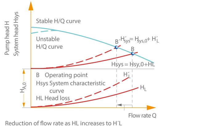
If the system characteristic curve becomes steeper as a result of throttling (H‘sys > Hsys), the flow is decelerated in the Valve, and the flow velocity and flow rate decrease. This occurs until a new balanced state (H‘sys = Hsys) is established, i.e. with a lower flow rate at operating point B‘ following the throttling action. This balancing behaviour is used to systematically control the flow rate.

Methods for systematically controlling the flow rate:

Changing the system characteristic curve

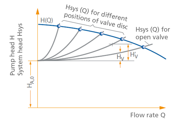
The system curve (system characteristic curve) is changed e.g. by means of a gate valve and other valves fitted in the piping which influence head losses. See Fig. 3 Closed-loop control

This is an embedded image

An increase in flow losses (H‘> HL) and the resulting change in the system characteristic curve lead to an intersecting point with the H/Q curve at a lower flow rate. See Fig. 2 Closed-loop control 

Control by throttling (i.e. by generating losses) is associated with high operating costs, since the system (piping) only requires part of the head generated by the pump (at low flow rates) while the other part is converted into non-usable energy.

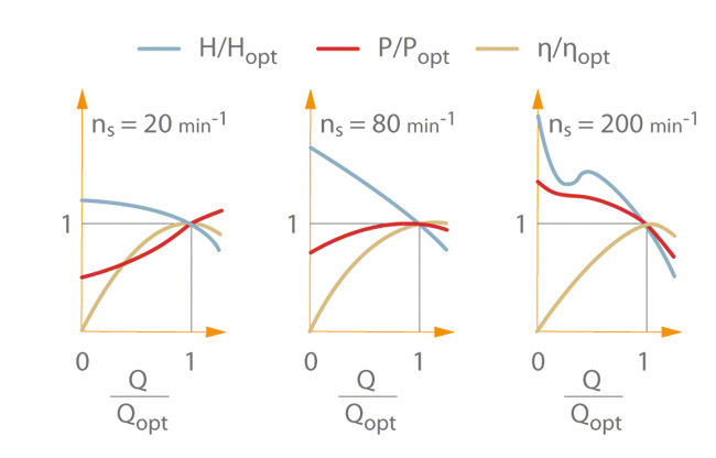
This control method is used primarily for relatively small centrifugal pumps, such as radial pumps, whose hydraulic performance is more permitting of such operation across their entire characteristic curves (see Operating behaviour and which are not operated at flow rates that greatly
deviate from the optimum flow rate over extended periods. In addition, the power input must decrease with flow rate as for some mixed-flow pumps (see Characteristic curve). 

Throttling should always be performed on the discharge side of the pump only, to avoid cavitation  in the centrifugal pump (see NPSH).

Throttling is an economically favourable type of closed-loop control in terms of investment outlay. Its overall economic efficiency should be checked, however, whenever higher power ratings and longer operating periods are concerned. This type of operation is required if the shut-off head of a centrifugal pump must be maintained to allow open-loop control (starting/stopping) using pressure-dependent control units. For longterm throttling applications a fixed orifice is frequently fitted in the piping in place of a throttling element or to assist it (see Valve). 

Changing the H/Q curve of the centrifugal pump

The H/Q curve of the centrifugal pump can be changed by implementing such measures as:

  • Controlling the rotational speed 
  • Changing the approach flow to the impeller by means of pre-swirl control measures, as for cooling water pumps
  • Changing the geometry of the centrifugal pump impeller by adjusting the impeller blade pitch (e.g. propeller pump
  • Trimming the impellers to match a specific duty point (change can only be made once and is irreversible)
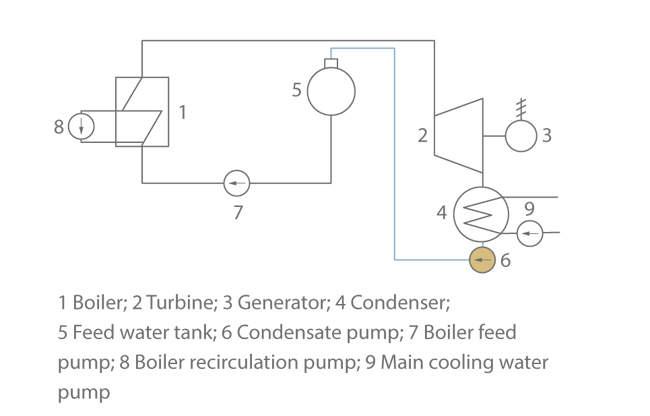
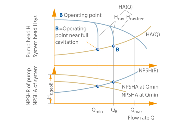
  • Self-regulation of the centrifugal pump resulting from cavitation See Fig. 6  Condensate pump
  • Adjusting the diffuser vanes in the diffuser (used less frequently)
  • Partially covering the outlet of radial impellers via regulating rings under low-flow conditions (used less frequently)

Only the pump head required by the system characteristic curve at the target point of the flow rate should be generated by the pump. In terms of operating costs, this type of closed-loop control is an economically efficient way of operating centrifugal pumps.

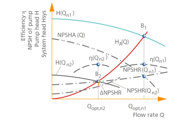
The H/Q curve (constant speed curve) of a centrifugal pump changes with rotational speed (n) as per the relationships expressed in the affinity laws (Q ~ n, H ~ n2). When rotational speed is changed, all points on the H/Q curve move on parabolas, e.g. operating point B1 moves on the parabola to B2. See Fig. 4 Closed-loop control

This is an embedded image

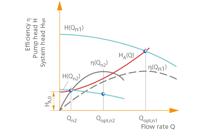
For system characteristic curves that pass through zero (Hsys = 0, Qsys = 0), the best efficiency point can move along the system curve in such a manner that the pump always operates at the optimum flow rate (Qopt).

The higher Hsys,0 is, the greater the risk of the pump operating at a poorer level of efficiency at low-flow conditions when flow rate is decreased, or at overload conditions when flow rate is increased. See Fig. 5 Closed-loop control

This is an embedded image

With speed control, only the head that is required is generated, which makes this control method the most energy-efficient and pump-friendly form of closed-loop control.

Rotational speed is most often adjusted by means of a drive such as a steam or gas turbine, a combustion engine (e.g. diesel engine), or an electric motor (field-regulated  direct current motor or  asynchronous motor with frequency inverter), and less often by a gear unit (e.g. controllable hydraulic torque converter or fluid coupling). 

On the inlet side of the centrifugal pump, a safety buffer is always provided for the NPSH available in the system when speed is reduced. See Fig. 4 Closed-loop control 

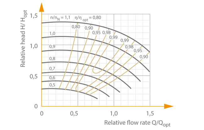
The inflow (see Inlet conditions) to a centrifugal pump impeller is typically free of swirl (see Vortex flow), i.e. for pre-swirl control equipment with controller position α = 90° (see Velocity triangle  which represents swirl-free inflow for cooling water pumps. See Fig. 10 Cooling water pump 

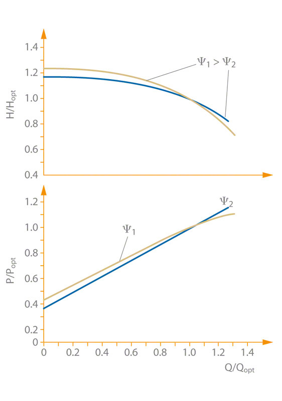
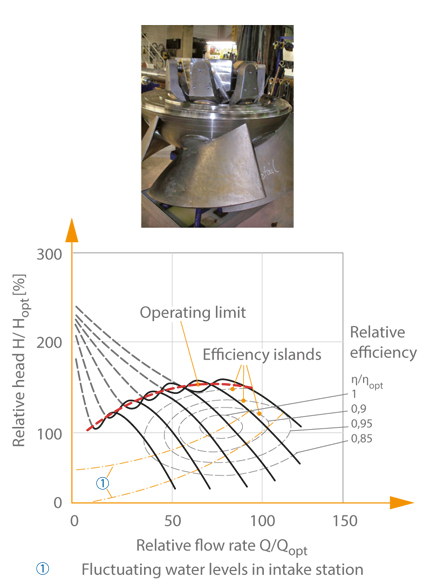
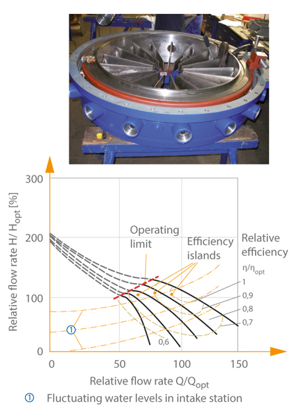
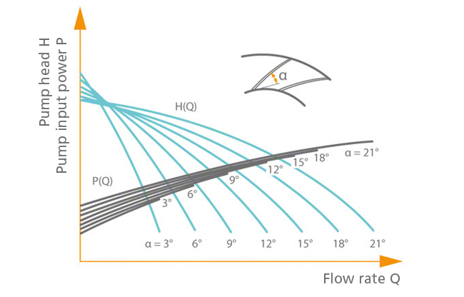
Co-swirling (in the direction of the impeller rotation) leads to a drop in the H/Q curve and power input of every centrifugal pump. While this barely impacts standard radial impellers, the effects of the change in inflow become more pronounced for mixed-flow and axial pumps as specific speed increases. As a result, pre-swirl control is particularly effective for mixed-flow pumps with high specific speeds when it comes to changing the H/Q curve to save power. Pre-swirl control equipment with inlet guide vanes can be infinitely adjusted. See Fig. 1 and Fig. 10 Cooling water pump

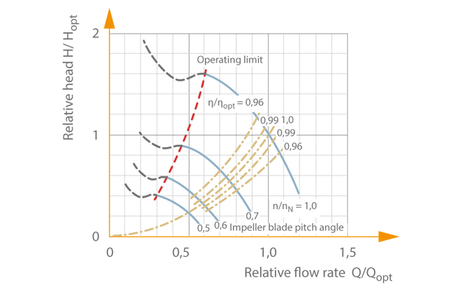
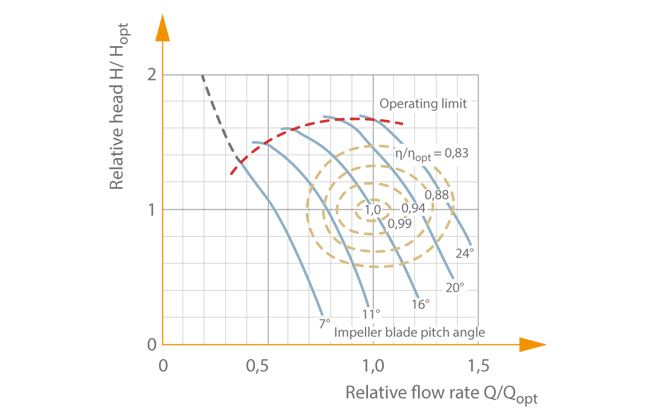
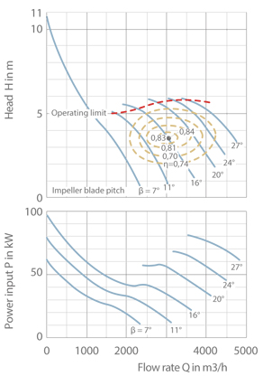
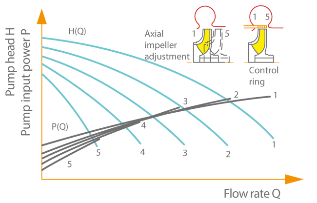
For propeller pumps, infinite adjustment is successfully achieved by means of impeller blade pitch control. See Fig. 6 Closed-loop control

This is an embedded image

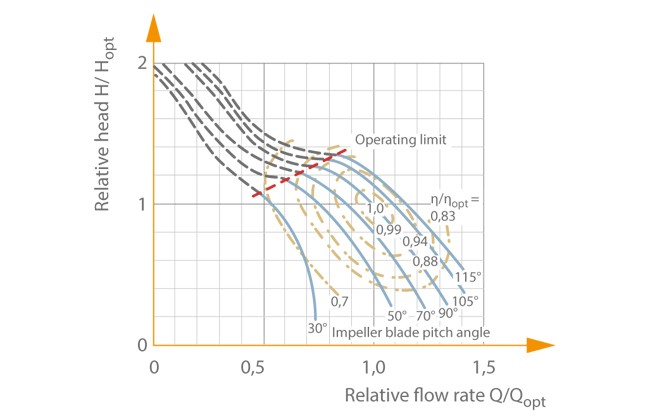
A much simpler but far less efficient approach is the less frequently used practice of adjusting the diffuser vanes on a radial centrifugal pump. See Fig. 7 Closed-loop control

This is an embedded image

By axially displacing the impeller or covering a part of its outlet section via a regulating ring, it is possible to partially restrict the impeller throughflow for control purposes. See Fig. 8 Closed-loop control 

This is an embedded image

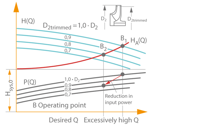
Trimming  impellers or reducing the impeller vane diameter  can only be regarded as control methods in the broadest sense of the word. While usually used to initially adapt a centrifugal pump to the pump system, these methods cannot be implemented during operation, nor reversed, unlike with genuine control measures. See Fig. 9 Closed-loop control
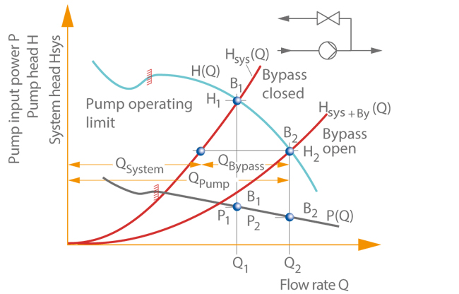
This is an embedded image

Bypass control

The type of closed-loop control whereby fluid travels through a centrifugal pump and system (piping) at different flow rates is known as bypass control (see Bypass) Such control is only beneficial for pumps whose characteristic power input curve drops as the flow rate increases. This is the case for  propeller and peripheral pumps, for example. See Fig. 10 Closed-loop control

This is an embedded image

Advantages and drawbacks of closed-loop control types

Power input is very dependent on the characteristic curves of the centrifugal pump and system such that specific examples cannot be generalised. 

A qualitative comparison can provide an overview of closed-loop control types with respect to power input. In one example, the flow rate (Q) is reduced by fifty percent. See Fig. 11 Closed-loop control

This is an embedded image

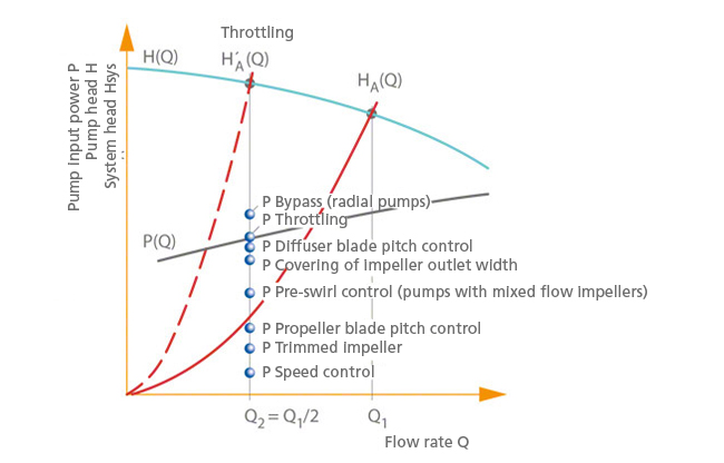
Bypass control requires the greatest power input for radial pumps, unlike with propeller pumps.

Graduating down to smaller power inputs, the most important types of closed-loop control are throttling, pre-swirl control, impeller blade pitch control (propeller blade pitch control), and speed control.

In summary, the diagrams reveal that the greatest amount of energy can be saved using slip-free speed control.

A disadvantage of energy-saving closed-loop control methods is the investment outlay, which is higher than that required for throttling. Efficiency calculations must be performed to decide which closed-loop control method should be used for the application in question.


*HV ≙ HL

Closed-loop test

In the context of centrifugal pump technology, the term "closed-loop test" refers to model testing and prototype testing of pumps and pump components carried out in a closed circuit (loop) on the pump test facility.

The opposite of the closed-loop test is the test with the pump mounted next to an open basin.

Coaxial cable

The coaxial cable, or coax cable, is a shielded cable. that is bipolar and concentric by design. It has an internal conductor (core), which is evenly spaced from a hollow cylindrical external conductor (see Cable shield). The two conductors are separated by an insulator or a dielectric, which can consist entirely of air.

Coaxial cables are used to transmit signals (e.g. laboratory and measuring instruments) and for broadband communication (e.g. transmitters, antennas). See Fig. 1 Coaxial cable

This is an embedded image


Collecting well

If individual wells have too low a yield (uneconomic pumping), the water from several boreholes is led into a collecting well via siphoning lines. By means of one or more centrifugal pumps the water in the collecting well is lowered in relation to the individual wells, and after evacuation of the siphoning lines (venting), water flows into the collecting well.

Colloid

A colloid is a particle or droplet dispersed in another medium, the dispersion medium.

Commissioning

Commissioning refers to the time when a machine or system is used for the first time by the operator, which is only permitted if compliance with the related requirements has been documented in accordance with relevant EC directives such as the Manufacturer's Declaration and CE marking.

In the context of centrifugal pump technology, to ensure fault-free pump operation, it is not only the condition of the pump that needs to be taken into account from the time of delivery up until the time of commissioning, but also the condition of all the components that come into contact with it (e.g. foundation).

Overall measures for fault-free operation 

General

  • Checking the pumps and their accessories to ensure that everything has been included in the delivery and that no damage has occurred in transit.
  • Organising and supervising proper and competent on-site transports of equipment to the pump foundation
  • Getting the pumps ready for operation
  • Checking all the equipment installed for the purpose of protecting the pumps
  • Instructing the customer's personnel regarding the functions and handling of the pumps and/or systems

Checks

  • Checking whether the dimensions of the foundations, recesses and passages are adhered to and in line with the approved foundation and general arrangement drawings
  • Checking whether the foundation bolts and frame are properly grouted without any shrinkage
  • Checking the flushing operation and pumps of the oil systems
  • Checking fine strainer inserts to be provided in inlet lines
  • Ensuring that pumps, gear units and motors are properly installed on the foundations without warping or twisting so that impermissible vibrations and premature damage are avoided 
  • Ensuring that piping connections are laid without subjecting them to any stresses or strains and carrying out any subsequent checks that may be necessary after adapting the piping
  • Alignment of pumps, gear units and motor couplings according to the manufacturer's instructions
  • Final precision alignment of pump, gear unit and motor, as well as monitoring this
  • Checking the direction of rotation 

Monitoring

  • Ensure assembly steps are carried out in the correct order as per the operating manual
  • Assembly of auxiliary systems (automatic recirculation valves and piping, oil supply and cooling systems)
  • Fill level of oil and bearing lubrication systems
  • Commissioning, test runs and trial operation including documentation of key operating data


Communications system

A communications system in the stricter sense of the term is a system that enables information and data to be transmitted. To this end, connections are established between multiple communication subscribers. Open communications systems allow all connected subscribers to communicate freely and require standardisation of interfaces and logical functions. In data networks, this is realised in hierarchical models with several standardised levels.

Information and data are typically exchanged between devices via application-specific bus systems that employ a strict protocol. An example of a standardised data protocol is VDMA standard sheet 24223 – Device Profile for Liquid and Vacuum Pumps.

Commutation

Commutation refers to the electric or electronic transfer of current from one element to another element (or phase windings in a direct current motor).

Condensate pump

A condensate pump is a centrifugal pump, which is named after the type of fluid handled. It is used in condensers to pump out the condensed steam as water (condensate) in a technical vacuum (near vapour pressure). In an open circuit, the condensate pump transports the condensate into a tank (e.g. feed water tank); in a closed circuit, it pumps the condensate directly into the boiler feed pump via a low-pressure feed heater. See Fig. 1 Condensate pump.

This is an embedded image

The maximum steam mass flow rate of the steam turbine determines the capacity (see Flow rate) of the condensate pump. 

Composition of the head: 

  • Geodetic head difference between the water levels in feed water tank and condenser
  • Difference of static pressure heads in feed water tank and condenser
  • Head losses of the flow in the pipeline, including installed valves (e. g. gate valve, swing check valve) and system components (e. g. suction strainer, condensate preheater)

The design of the condensate pump is governed by the vapour pressure of the water on the suction side (for pure water at 35 °C approximately 56.2 mbar) and by the low inlet head resulting from the position of the condenser within the structure. The inlet head is calculated by subtracting the flow losses in the inlet line from the geodetic head between the standard water level in the condenser and the level of the impeller of the first stage. 

To achieve an optimum operating behaviour and prevent cavitation damage the available NPSH of the system must be greater or equal to the required NPSH at the impeller of the first stage. This applies to the entire operating range.

Measures to increase the system-side inlet head:

  • Minimising the flow losses in the inlet line; e. g. by means of larger nominal pipe diameters
  • Vertical arrangement, e. g. dry installation, which reduces the height of the first-stage impeller above the installation floor and increases the difference in geodetic head.
    See Fig. 2 Condensate pump
  • Vertical arrangement as a "can-type pump", in which the geodetic head difference is increased by lowering the suction stage into an inlet "can" arranged below the installation floor.
    See Fig. 3 Condensate pump
    The inlet and discharge lines are arranged above the installation floor.

This is an embedded image

This is an embedded image

Options of enhancing the suction characteristics of a condensate pump: 

One design variant is that of a condensate pump with intermediate extraction (re-entry). After the first or second stage of the pump (condensate booster pump with single or double entry suction stage) the entire flow is diverted to the condensate cleaning system. See Fig. 4 Condensate pump

This is an embedded image

The pressure is further increased in the condensate main pump, which is installed above floor, above the booster pump with which it forms a unit.

For flow rates exceeding 150 l/s (540 m3/h) high cavitation loads require particular consideration of the intensity of cavitation, velocity conditions and lengths of the occurring trail of cavitation bubbles. The intensity of cavitation can be measured by means of the material loss rate LM.

This is an embedded image

The exponent values depend on the design concept of the suction stage impeller. They lie within the following range:

This is an embedded image

As the flow velocity at the impeller vane leading edge at a given flow rate cannot be greatly influenced, the lengths of the bubble trails have to be reduced as far as possible.

The shaft seal of condensate pumps must provide sealing against a low technical vacuum during standstill of the pump. This requires the sealing element  to be fed with barrier fluid from the system-side barrier system in order to prevent air ingress. In the case of gland packings, a lantern ring is inserted between the packing rings for this purpose. Mechanical seals are designed as inboard and outboard double mechanical seals. The barrier fluid is supplied to either the lantern ring or the chamber between inboard and outboard mechanical seal.

Three-phase motors with squirrel cage are generally used as drives of condensate pumps, if they are suitable for operation with a closed loop control system. The following control options are available to adjust the pump to fluctuating turbine loads and to prevent dry running of the condensate pump.

Options of controlling a condensate pump:

  • Adjusting the system characteristic curve by means of throttling with a control valve in the discharge line
  • Adjusting the system characteristic curve by returning excess flow to the condenser (bypass adjustment) (see Bypass)
  • Adjusting the H/Q curve by altering the pump speed (speed control)
  • Adjusting the H/Q curve by letting the flow rate adjust itself to the inlet head (see Suction characteristics). This type of control based on incipient cavitation is also known as "self-regulation". See Fig. 5 Condensate pump

This is an embedded image

The self-regulation of condensate pumps exploits the change in the characteristic curve H(Q) with part of the condensate evaporating upstream of or in the first stage, which reduces the head H(Q) of this stage by a certain amount depending on the extent of blockage by steam (Hcav). Depending on the water level Hz.geo a head breakdown curve (influenced by the extent of cavitation Hcav(Q) is established, whose intersection with the system characteristic Hsys(Q) determines then operating point (OP).

Due to the high cavitation loads, self-regulation of condensate pumps imposes arduous requirements particularly on the first stage of the pump. For this reason this type of regulation is no longer adopted on the larger pumps which are commonly used today.

Condition monitoring

Condition monitoring is a concept for keeping track of a product's states so that safety and machine efficiency can be ensured. Within this context, sensors are used to take regular measurements in order to provide meaningful values such as vibration and temperature data.

For this purpose, condition monitoring relies on the infrastructure of a communications system. Condition monitoring is based on analysing sensor data in real time. It is these data that make it possible to implement a reliable and highly responsivesafety system (e. g. for emergency shutdown). This enables precise analysis of the disruptive factors so that all you have to do is replace the destroyed component. Before the advent of this new concept, (preventive) maintenance was carried out at set intervals, which meant that even fault-free components were replaced in certain circumstances. See Fig. 1 Condition monitoring

This is an embedded image

Aspects of condition monitoring 

  • Condition detection (measurement and documentation of the current machine values)
  • Condition comparison (comparison of actual values with reference values (e.g. limits or setpoint values)
  • Diagnostics (pinpointing of any errors that may be present with a view to planning necessary maintenance measures)

Constant level oiler

A constant-level oiler is used to check the lubricant quantity (e.g. in rolling element bearings). As long as the reservoir contains oil, the oil level in the bearing housing is sufficient to ensure reliable lubrication.

The reservoir should be kept at least one third full in order to ensure that the oil level in the bearing is guaranteed for a prolonged period of time. 

See Fig.1 Constant-level oiler

This is an embedded image


Contactor

The contactor is an electrical or electronic switch specially designed for high levels of electrical power. It has two switching positions and typically operates in the monostable mode. Contactors differ from relays in three major respects.

Differences to relays:

  • Relays are only designed for lower and contactors for higher switching capacities.
  • Relays have single-break contacts whereas contactors have double-break contacts.
  • Relays have hinged (clapper-type) armatures while contactors have plunger-type armatures to exert greater mechanical force to switch the larger contacts required for the higher switching capacity.

Continuity equation

The continuity equation is one of the fundamental equations applied in fluid mechanics. It defines the conservation per unit of time of a flow volume through a given cross-section. For fluid flowing through a pipe, the flow velocity is inversely proportional to the pipe cross-sectional area.

The continuity equation stipulates that the sum of all flow volumes entering a defined space (positive sign) equals the sum of those leaving it (negative sign).

Control by throttling

Control by throttling is used to influence the flow rate in a pump system by varying system resistance. It is also the simplest way to shift the operating point of a centrifugal pump because it uses existing valves fitted inside, upstream, or downstream of the system. Unwanted noise and vibrations can occur, however, and control by throttling is the least energy-efficient control method (control by generating losses).

Control unit

The control unit is the heart of  open-loop control systems. and comprises electrical and electronic components that are wired such that they can execute complex control processes automatically.

Today's control units are based on microprocessors or PLCs basiert. In pumps, they can execute the more complex switching and control processes as they occur in a multiple-pump system in a manner that is compliant with the application. See Fig. 1 Control unit

The pump know-how required is implemented as software based on mathematical algorithms. These pump control units are used for pressure booster systems for example, whereby one or more pumps are started and stopped in line with fluid requirements (pressure, flow rate) to safeguard proper and reliable operation of the system. See Fig. 2 Control unit

This is an embedded image

This is an embedded image


Controlled gap seal

The controlled gap seal is a seal frequently used on centrifugal pumps  between rotating and stationary pump components. The gap's width (clearance gap width) and shape are designed to minimise the mass flow which can pass through it (see Clearance gap loss)

Examples are the sealing of the individual stages of multistage pumps against one another or in balancing devices and the sealing of the impeller's suction side against the discharge side. (see Clearance gap pressure). 

The width of the controlled gap seal affects both the economic efficiency and the operating reliability of a centrifugal pump and depends on the following factors: shaft deflections, vibrations (including self-induced vibrations), nature of fluid handled, degree of contamination, grain size of the dirt particles (see abrasion), temperatur. If the thermal expansion of the rotating components differs from that of the stationary components, the clearance gap width may change and under certain conditions the casing may even be distorted.

The main types of controlled gap seals used in centrifugal pump engineering are smooth controlled gap seals, stepped controlled gap seals and labyrinth seals. Convex (curved towards the outside) and conical (in the shape of a cone) gaps have proved their worth in applications such as bottle cleaning systems where the removal of labels presents a risk of clogging.

Controller

A controller automatically influences a variable in a technical process based on a setpoint. To this end, this variable is first measured (actual value) and compared to the setpoint, then a control value is calculated from the difference and used to minimise the control deviation (also see Closed-loop control). 

One type of controller is the PI controller.

Cooling water pump

Cooling water pumps are used for supplying heat exchangers with cooling water. Their flow rate varies depending on the heat flow to be dissipated. The required head is determined by the type of cooling system.

A distinction is made between wet cooling and dry cooling processes.

Range of head and flow rate 

The required heads for fresh water operation usually lie within 5 to 15 m. In cooling tower operations they can be as high as 20 to 35 m.

The flow rate depends on the cooling process, the characteristics of the heat exchanger and on whether the pump is to be installed in a fossil-fuelled or a nuclear power station.

Reference values

  • Cooling with fresh water (see Wet cooling):
    fossil-fuelled power station 100-120 m3/MW
    nuclear power station 140-160 m3/MW
  • Indirect cooling with air (see Dry cooling):
    fossil-fuelled power station 80-100 m3/MW
    nuclear power station 120-140 m3/MW

Impeller types

The required range of heads ranging from 5 to 35 m is covered by three types of impellers.

  • Range of head per impeller type
  • Up to 10 m axial propellers are generally used (specific speed ns > 150 rpm)
  • From 10 to 25 m mixed flow propellers can be used (100 rpm < ns < 150 rpm)
  • From 10 to 40 m diagonal impellers (mixed flow impellers) are used (70 rpm < ns < 150 rpm)

Naturally, all three types can also be installed in multistage pumps, which will extend the head range. However, a multistage design will always be more costly. It is only selected if such a type of pump is required to control the flow rate.

Type of pump

Cooling water pumps are usually vertical shaft tubular casing pumps or volute casing pumps which are made completely of metallic materials.

See Figs. 1 to 4 Cooling water pump

This is an embedded image

This is an embedded image

This is an embedded image

This is an embedded image

Less frequently, submersible motor pumps are also employed as cooling water pumps, e.g. with a mixed flow impeller (see Impeller). See Fig. 5 Cooling water pump

This is an embedded image

For economic reasons, concrete casings are also chosen for volute casing pumps from DN 1200 to DN 1400 (see  Nominal diameter) and for tubular casing pumps up to approximately DN 2000. In this case, the volute or tubular pump casings (see Pump casing) are partly or completely made of concrete. See Figs. 6, 7 Cooling water pump

This is an embedded image

This is an embedded image

The following impeller types are suitable for tubular casing pumps:

  • Mixed flow impeller See Fig. 1 Cooling water pump
  • Mixed flow propeller See Fig. 2 Cooling water pump
  • Axial flow propeller See Fig. 3 Cooling water pump

Impeller types for volute casing pumps:

  • Mixed flow propeller
  • Mixed flow impeller, see Fig. 4 Cooling water pump

On board vessels (see Marine pumps) cooling water pumps with volute casings are also fitted with double-entry radial impellers (see Double-suction pump). See Fig. 8 Cooling water pump

This is an embedded image

Closed-loop control

In some cases a cooling water pump has to be controlled to react to changes occurring during the cooling process.

Reasons for controlling a cooling water pump:

  • Adjusting the flow rate at constant head to the changing conditions in the heat exchanger (e.g. part load of the turbine)
  • Adjusting the head at constant flow rate, if the pump head fluctuates with the water level on the suction side or if the operation changes over from fresh water to cooling tower operation
  • If, after a pump failure, the remaining pumps are to pump 100 % of the cooling water flow

Cooling water pumps can be controlled in various ways: 

Throttling 

  • Closing a throttling element (see Valve) in the discharge line (see Pump system) increases the head of the system and decreases the flow rate.
  • There are limits to this type of control, as for specific speeds of ns > 100 rpm the pump power input increases with decreasing flow rate and may exceed the motor power available.
  • In addition, the flow will separate from the vanes under specific low-flow conditions (see Operating behaviour) and the pumps will run rough (see Smooth running), which must definitely be avoided for continuous operation.
  • Of the control methods described in this section, throttling generates the highest losses. Its use is generally confined to very small units. Throttling is not common in today's modern power stations.

Speed control

  • Speed control is used for adjusting the rotational speed of the pump. As a result, the head, flow rate and pump input power are adjusted in accordance with the affinity laws. However, the greater the static component (HS,0) of the system head (HS) (see System characteristic curve) the more the operating point deviates from its optimum at reduced speed. In other words, it shifts toward low-flow operation and, hence, toward the cut-off point. See Fig. 4 Closed-loop control
  • Speed is either controlled directly or via a speed modulation gearbox. Three-phase motors are frequently selected as drives. Direct current motors are generally not suitable due to the large amounts of pump input power required for cooling water pumps.
  • Lately, motors with frequency inverter have increased in popularity, also for larger ratings.
  • Thyristors are used for electric speed control of three-phase motors with large ratings. 

Impeller blade pitch control

  • This type of control is suitable for pumps with axial and mixed flow propellers. The impeller vanes are adjusted during pump operation.
  • The characteristic curves selection chart of such pumps with all possible adjustment angles generally shows elliptically shaped efficiency curves with almost horizontal
    principal axes. See Fig. 9 Cooling water pump
  • This is the optimum type of control in cases where large changes in flow rate at relatively small variations in head and an almost constant efficiency are required.

This is an embedded image

Pre-swirl control

  • This type of control is used for pumps with mixed flow impeller. The flow upstream of the impeller is influenced by imparting pre-swirl. The flow rate is increased by inducing pre-swirl in the same direction as the impeller rotation or decreased by inducing pre-swirl in the opposite direction. This is effected by a stationary vane cascade with adjustable pitch angle, fitted upstream of the impeller. See Fig. 1 Cooling water pump
  • The selection chart of such pumps with all possible pre-swirl angles generally shows elliptically shaped efficiency curves. The principal axes run (roughly) parallel to the pump characteristic curve. They differ in this respect from the ellipses of impeller blade pitch control, whose principal axes run almost horizontally. See Fig. 10 Cooling water pump
  • This is the preferred type of control in cases where relatively small changes in flow rate at large variations in heads and optimum pump efficiencies are required.

This is an embedded image


Coriolis force

The Coriolis force is an inertial force which acts on bodies that move in a rotating reference frame. The direction of the Coriolis force is perpendicular to the direction of movement of the body and to the rotational axis of the reference frame. If the direction of movement and the rotational axis are parallel, this force is zero.

Corrosion

Corrosion is the reaction of a metallic material with its environment, according to ISO 8044 and VDI 3822. In most cases the reaction concerned is electrochemical and can only take place in the presence of ion-conducting solutions (electrolytes). This is called a redox reaction, since it is divided into two parallel semi-reactions: anodic oxidation (dissolution of the metal) and cathodic reduction of ions in the electrolyte.

This results in measurable changes in the material, which may lead to a breakdown of the component or system (see Damage). This may be reduced or prevented by corrosion protection Different types of damage result from various types of corrosion. The most common types of corrosion and their manifestations in aqueous media are:

Without mechanical loads

  • Uniform surface corrosion is a form of corrosion with nearly uniform material loss rate on the entire surface. See Fig. 1 Corrosion
  • Shallow pit formation, on the other hand, is characterised by localised attack of the surface. It is caused by local variations in corrosion impact (temperature, concentration, flow velocity) with formation of corrosion products of variable solubility. See Fig. 2 Corrosion
  • Pitting corrosionis a very localised electrolytically induced material loss that leads to the formation of holes (pitting). Pitting can occur in the presence of corrosion cells (see DIN 50900, Part 2), particularly in liquids with chlorides and especially on stainless steels and on aluminium alloys. See Fig. 3 Corrosion
  • Crevice corrosion is found in small crevices between metals of the same type or between metallic and non-metallic materials. There is a corrosion cell that is frequently formed by concentration of chlorides in the crevice, or by depletion of oxygen in the crevice thus preventing the formation of a protective oxide layer.
  • Galvanic corrosion is caused by the formation of a corrosion cell between metals with different free corrosion potentials, where the less noble metal is anodically dissolved more quickly and the more noble forms the cathodic surface for the reaction. The corrosion rate depends on the difference in corrosion potentials between the two metals, and the ratio of reaction surface areas of the two materials. Combining small anode surfaces and very large cathode surfaces should therefore be avoided, especially when the difference in free corrosion potentials is very large.
  • Selective corrosion is a type of corrosion in which only certain parts of the material structure are corroded, e.g. areas near the grain boundaries or alloy components. Examples of selective corrosion include spongiosis (graphitisation), intergranular corrosion, dezincification and dealumination. See Figs. 4, 5 Corrosion
  • Spongiosis (graphitisation) is an example of selective corrosion of cast iron caused by the dissolution of ferrite and perlite due to the lack of protective layer formation. The original shape of the part is preserved by the graphite skeleton filled with corrosion products. See Fig. 6 Corrosion
  • Intergranular corrosion is the preferred corrosion attack of the areas near grain boundaries. In stainless steels it is caused by chromium depletion due to carbides precipitating on the grain boundaries. Intergranular corrosion can lead to rapid intergranular attack (grain disintegration). See Fig. 7 Corrosion
  • Dezincification or dealumination is the selective corrosion of zinc-rich or aluminium-rich phases in non-ferrous metals.
  • Downtime corrosion occurs in stagnant fluids and only develops during a plant's non-operating periods.
  • Microbial corrosion is caused by microorganisms, e.g. by sulphate-reducing bacteria.

This is an embedded image

This is an embedded image

This is an embedded image

This is an embedded image

This is an embedded image

This is an embedded image

This is an embedded image

With mechanical loads

  • Erosion corrosion is a combination of mechanical wear (see Abrasion) and corrosion, where corrosion is facilitated by the destruction of protective layers as a result of the erosion. See Fig. 8 Corrosion
  • Cavitation corrosion is a combination of cavitation and corrosion, where the corrosion is either initiated or accelerated by local destruction of protective layers by cavitation. See Fig. 9 Corrosion
  • Fretting corrosion is caused by mechanical wear and damages protective or passive layers in a corrosion attack of an aggressive fluid.
  • Stress corrosion cracking occurs as cracks in metals when exposed to various tensile stresses in certain corrosive media. The brittle fracture of the material without any visible corrosion products is a feature of stress corrosion cracking. See Stress corrosion cracking, Figs. 11, 12
  • Corrosion fatigue is a brittle, mainly transgranular crack formation in metals caused by the interaction of mechanical cyclic stresses and corrosion. See Fig. 12 Corrosion

This is an embedded image

This is an embedded image

This is an embedded image

This is an embedded image

This is an embedded image

Further terms

  • A corrosion cell is a galvanic cell that consists of a cathode and an anode, which are metallically conductive and electrolytically connected. This cell can be caused by a combination of different metals (galvanic corrosion), different phases in one material (selective corrosion), local aeration and local ion concentration (crevice and pitting corrosion). Electrochemically less noble metals, material phases, etc. act as anodes (metal ions pass into the electrolyte) and the electrochemically more noble metal acts as the cathode surface (cations from the electrolyte are reduced). Even on homogeneous metal surfaces local anodes and cathodes can be formed by locally different aeration or deposits of corrosion products.
  • Electrode potential is the electric potential of a metal or an electron-conducting solid in an electrolytic solution. The electrode potential can only be measured as a voltage against a reference electrode. See Fig. 13 Corrosion
  • A reference electrode is an electrode that keeps its electrode potential constant even when exposed to outside voltages. The potential of the reference electrode refers to the potential of the standard hydrogen electrode.
  • Free corrosion potential (rest potential) is the potential shown on metal wetted with electrolyte without the effects of external electric currents.
  • Pitting corrosion potential is the critical potential where pits start to grow constantly in number and size.
  • Repassivation potential is the critical potential below which pits stop growing and start to repassivate.
  • Passivation is the transition of a metal from the active to the passive corrosion state (passivity). Passivation can be caused by electrochemical or chemical reactions.
  • Passivity occurs when the anodic metal dissolution decreases under stationary conditions, such as when the electrode potential is shifted to more noble values or the concentration of dissolved, oxydising substances in the solution is increased. Due to this, a thin, closed oxide layer is formed on the surface of the wetted metal (passive layer, protective layer), which greatly reduces further metal dissolution and gives good corrosion resistance to electrochemically non-noble noble pure metals and metal alloys (see Chemical resistance table).

This is an embedded image


Corrosion protection

Corrosion protection can be effected by the corrosion itself and by cathodic protection.

Protection by corrosion

Corrosion protection may be activated by corrosion itself, when uniform layers of reaction products form a protective layer on the surfaces. Corrosion protection can also be achieved by keeping the metallic material separated from the corrosive medium by applying protective layers or by electrochemical means such as cathodic protection.

Cathodic protection

Cathodic protection is an electrochemical process in which the metal surface is polarised to a non-precious potential, so that the reduction reactions can then take place on the resulting layer. The corrosion rate is relatively low as a result and local corrosion phenomena are prevented.

Methods of cathodic protection

  • The metal to be protected is electrically connected with a second, less noble metal and both are immersed in the corrosive medium. A corrosive cell is formed, in which the less noble metal dissolves anodically (protection anode) and has to be renewed at intervals, whereas the more noble part is protected cathodically.
  • The metal to be protected is connected to the negative pole of a direct current voltage source and forms an electric circuit with an inert anode and the medium.

Corrosion rate

The corrosion rate indicates the velocity at which corrosion progresses. It is dependent, for example, on the ratio of surface areas to one another and on the molar concentration. The corrosion rate thus increases with rises in current density.

Costs

From a business administration perspective, costs are any type of expenditure that can be expressed in monetary terms, including the consumption of resources for the purpose of completing tasks. In addition to loss of value due to wear and tear (depreciation) they also include human resource expenses, physical resource expenses and service expenses (also see Economic efficiency).

Counter-clockwise impeller

The counter-clockwise impeller is an impeller, which rotates counter-clockwise as viewed from the inlet flow direction (also see Rotational speed). In accordance with the EU 12723 standard, the terms 'left- or right-handed impellers' are no longer used.

Counter-clockwise and clockwise, viewed from the direction of the drive, are now the standard terms.

Countershaft

The term countershaft refers to an auxiliary gear unit that reduces the number of revolutions of the driven shaft, thereby increasing the available torque. It is usually unsynchronised and so shifting is only possible at standstill and with no load.

Coupling alignment

Coupling alignment is essential to ensure the trouble-free mechanical operation of a pump set and to avoid damage to the transmission elements. It involves maintaining the prescribed distance (a) between the coupling halves (see Shaft coupling). See Fig. 1 Coupling alignment

This is an embedded image

Furthermore, the shaft centrelines must be precisely aligned with one another at the coupling, and any lateral, height or angular misalignment must be compensated. See Figs. 3, 4 Coupling alignment

This is an embedded image

This is an embedded image

The alignment should be checked, preferably by means of a straight-edge and feeler gauge. See Fig. 1 Coupling alignment

A coupling is correctly aligned if a straight-edge laid across both coupling halves parallel to the shaft maintains the same distance from the shaft at all points around its circumference. In addition, the axial distance between the coupling halves should remain the same at all points around the circumference.

Accurate alignment can be achieved quickly using an alignment jig. See Fig. 2 Coupling alignment

This is an embedded image

The required degree of coupling alignment accuracy depends mainly on the coupling type and the rotational speed In the case of hot water pump coupling alignment, it is important to observe the pump manufacturer's special instructions relating to thermal deformations associated with hot water pumps. After completing coupling alignment, it is advisable to pin the pump incl. drive to the baseplate or pump foundation, to prevent shifting of the pump set during operation.

CPU

CPU stands for Central Processing Unit, which is the control and arithmetic unit of a computer or automation unit.

Critical speed

Critical speed (nk) is the rotational speed at which acting dynamic forces cause a machine component (e.g. shaft, rotor) to vibrate at its natural frequency (also referred to as intrinsic frequency, fi) and can even result in resonant vibrations throughout the entire machine and pump set. This effect has the potential to damage fast rotating machinery but can be minimised when such rotational speeds are passed through quickly. See Fig. 1 Critical speed

This is an embedded image

In a broader sense, critical speed is also known as the rotational speed at which the frequency of a pulsating torque coincides with the natural torsional frequency of the shaft assembly.

Current requirement of electric motors

The average current requirement (J1 in A) of standard three-phase current squirrel-cage motors (see Asynchronous motors) and direct current motors depends on the motor rating (see Drive rating), motor speed, voltage and power factor.

See Fig. 1 Current requirement

The submerged motor as a wet rotor motor, like the submersible motor, consumes slightly more energy than a dry three-phase current squirrel-cage motor due to the inherent fluid friction and larger gap. The average energy requirement is specified for pole numbers  2 and 4 and for the three-phase system frequency (f) of 50 Hz.

See Figure 2 Current requirement

Canned motors experience additional loss in the can, which further increases the average current requirement.

Current transformer

A current transformer is a special transformer used to measure large alternating currents and has only one or a few primary windings, which are energised by the current to be measured, and at least one secondary winding. This current is reduced in reverse proportion to the ratio of primary and secondary windings and can now be processed further using available measuring instruments or electronic circuits. The secondary winding is connected to a current sensor or the current path of an energy counter, for example. The resistive load connected to the secondary winding for the current measurement must not exceed a set value to ensure an accurate measurement result. This is referred to as the burden.

Current transformers are not suitable for measuring direct current. However, current sensors capable of measuring direct current, and based on Hall sensor technology are also regarded as current transformers.

Cyclone

The cyclone is a separator device that uses centrifugal force to remove solids and liquids from gases. Hydrocyclones are used for separating solids from a fluid. By tangential injection of the pressurised, contaminated liquid into the rotationally symmetric chamber of the cyclone, a centrifugal force field is created.

This causes heavy particles to gather near the outer wall, from where they are extracted downwards via a narrow, funnel-shaped opening. The cleaned liquid can then be removed upwards from the centre of the cyclone. See Fig. 1 Cyclone

This is an embedded image

Cyclones are used in centrifugal pumps to clean lightly contaminated fluids handled without great cost, for use as bearing lubricant (e. g. plain bearing)  or as barrier fluid for seals (e. g. shaft seals).