Magnetic coupling
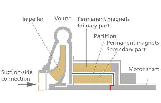
A magnetic coupling can be used to transfer power to centrifugal pumps. It consists of a primary part which is rigidly connected to the motor shaft, and a secondary part which is arranged on a shaft (see Pump shaft) together with the impeller.
Both the primary and the secondary parts are fitted with permanent magnets. Poles of opposite polarity face each other. They attract each other due to the magnetic flux. When the primary part is driven, the secondary part rotates synchronously (at the same rotational speed).
Centrifugal pumps with magnetic couplings are also referred to as mag-drive pumps magnetic drive pumps or magnetic pumps. These days they can be designed with power ratings as high as 400 kW.
See Fig. 1 Magnetic coupling
See Fig. 1 Magnetic coupling

Fig. 1 Magnetic coupling: Schematic
When the torque, to be transmitted increases, the angular displacement or load angle between the axes of the magnets of the primary part and the secondary part will also increase. If the torque to be transmitted exceeds a given maximum value (decoupling torque), the coupling will break out of sync and the secondary part will come to a standstill. In this case, the drive must be switched off as run-up requires the two parts to be in synchronisation.
This disadvantage can generally be ignored for centrifugal pump sets with a suitable drive rating. It can be avoided altogether by using a secondary part which is designed like the squirrel-cage rotor of an asynchronous motor. This design allows for asynchronous run-up and operation.
A partition (occasionally a double partition for safety reasons) is fitted in the gap between the primary part and the secondary part of the magnetic coupling (double-walled containment shell) and seals the pump hermetically. For this reason, the applications centrifugal mag-drive pumps are used for are similar to those of canned motor pumps. See Fig. 3 Chemical pump
Magnetic couplings must not be confused with the electromagnetic clutches used for control purposes or for protection against shock loading.
