P

Parallel operation

Parallel operation, or parallel pumping, of two centrifugal pumps is a mode which allows pump operation to be controlled by starting or stopping one of the two pumps.

If two centrifugal pumps I and II are operated in parallel, the flow rate QI+II is the sum of the flow rates of the individual pumps at the same head, i.e.:

This is an embedded image

The actual flow rate and head of pumps operating in parallel (operating point)  is the intersection of the common pump and system characteristic curvesSee Fig. 1 to 5 Parallel operation

Each pump must be secured with its own check valve (see Valve). Centrifugal pumps run in parallel will operate without any problems if theirn characteristic curves are stable and both have the same or almost the same shut-off head. See Fig. 1 Parallel operation

This is an embedded image

Trouble-free operation does not necessarily require that the pumps exhibit the same characteristic curves (H/Q). When QI+II decreases to Q´I+II, then the individual flow rates QI and QII also decrease to Q´I and Q´II. If the shut-off heads (H0) of pumps I and II are different, pump I is rapidly pushed towards the shut-off point while pump II continues pumping. See Fig. 2 Parallel operation

This is an embedded image

In the case of two centrifugal pumps I and II with unstable characteristic curves and the same peak heads (Hpeak), parallel operation is possible in the range 4 to 5 where any further pump of the same characteristics can cut in without any problems. See Fig. 3 Parallel operation

This is an embedded image

At point 4, one other pump of the same characteristics can be started due to the shut-off head (H0). Between points 4, 3, 2 and 1 down to almost 0, this is no longer possible. In these operating ranges the pump, whose shut-off head (H0) is smaller than HI+II, would not be able to open the check valve because of the pressure exerted on it by the other pumps.

A further example of pumps in parallel operation shows two centrifugal pumps I and II with unstable characteristic curves where the peak head (Hpeak) of pump I is higher than that of pump II. As soon as the head at the operating point (HI+II) is higher than the smallest value of the peak head (HpeakII) parallel operation will lead to a very complex transient flow pattern. When starting parallel centrifugal pumps with unstable characteristic curves and different shut-off heads, the pump with the smaller shut-off head (H0II) will not be able to open its check valve against the pressure of the other pump (H0I > H0II) and must therefore be started first.
See Fig. 4 Parallel operation

This is an embedded image

This type of constraint can lead to interruptions in pump operation and should be eliminated by meticulous planning right from the start.

If parallel operation of two pumps is not specified, it is easier and less costly to design a double-suction pump instead of using two separate centrifugal pumps.

If a plunger or piston pump and a centrifugal pump are operated in parallel, the flow rate of the piston/plunger pump (QK), which is almost constant over the head, is added to the centrifugal pump's flow rate (QI). See Fig. 5 Parallel operation

This is an embedded image


Pendulum-type electric motor

The pendulum-type electric motor of a machine (e.g. centrifugal pump) or the pendulum-type generator of a prime mover (e.g. water turbine) offers very precise measuring options for quantifying torque when configured properly. This variable is determined by quantifying the reluctance torque (counter torque) at the stator of the motor or generator through taking a weight measurement for the known lever arm. To this end, the stator of the pendulum machine must be pivot-mounted about the machine axis. A double bearing arrangement comprising ball or roller bearings is typically used for this purpose (see Rolling element bearing).

If measurement accuracy requirements are very high, the "outer bearings" should be of the hydrostatic (current-free fluids) or aerostatic (current-free gases) type so that only the torque output to the machine or the torque from the prime mover is measured. See Fig. 1 Pendulum-type electric motor

This is an embedded image

Various losses that occur inside the outer bearings do not influence the measurement. It is therefore beneficial to connect all sources of loss irrelevant to the scenario (e.g. pump bearings) to the oscillating part (stator) for very high measurement accuracy requirements.

Performance coefficient

The performance coefficient (λ) is a characteristic coefficient identifying the pump input power.
The following equations are yielded in conjunction with the pump power output (PQ) and pump input power (P):

This is an embedded image

ρ    Density of fluid handled
η    Pump efficiency
U2   Circumferential velocity at the impeller outlet
D2   Impeller diameter at the outlet
b2   Impeller outlet width
φ    Flow coefficient
ψ    Head coefficient

Peripheral pump

Peripheral pumps, also referred to as regenerative pumps (also see Side channel pumps), are centrifugal pumps whose impeller (see Peripheral impeller) rotates in a largely concentric casing channel with an inlet and an outlet opening. As the fluid handled repeatedly circulates between the impeller and the casing channel the energy transferred to it is very high.

In total the fluid moves along the circumference from the inlet to the outlet of the casing with increasing pressure. A stripper arranged between the outlet and the inlet prevents a hydraulic short circuit between the high-pressure and the low-pressure side of the casing channel.

Due to the large increase in energy, peripheral pumps can be relatively small in size. They are often designed as close-coupled pumps.

See Figs. 1, 2 Peripheral pump

This is an embedded image

This is an embedded image

The head coefficients, or pressure coefficients, of peripheral pumps exceed those of side channel pumps and their characteristic curves are steeper. The pump input power of peripheral pumps decreases with increasing flow rate.

Peripheral pumps with several (up to three) blade wheels arranged at the various diameter levels of the impeller are considered multistage pumps. At common speeds of 2,900 rpm they produce heads of up to 1,200 m. For low flow rates peripheral pumps can partly be used for the same applications as high-pressure geared pumps (see Geared pump) and even positive displacement pumps. See Fig. 3 Peripheral pump

This is an embedded image

Another characteristic of peripheral pumps is that, unlike other centrifugal pumps, they can transport fluids with a relatively high gas content (see Two-phase flow). Even severe vapour bubble formation (see Cavitation) will not lead to flow cut-off or have a major impact on the pump's smooth running. The H/Q curve will deviate gradually rather than suddenly from the H/Q curve measured in cavitation-free conditions. Another advantage is the symmetrical approach flow (see Double-suction pump) to the impeller (low axial thrust). See Fig. 4 Peripheral pump

This is an embedded image

The efficiencies of peripheral pumps are lower than those of radial pumps. They are suitable for pumping uncontaminated liquids, e.g. as boiler feed pumps for small boilers, as pressure boosting pumps, car wash pumps, as pumps for the chemical industry and for all applications in which low flow rates have to be pumped at high pressure.

pH value

The pH value, according to DIN 38404 (Part 5, 2009 edition), is the negative decimal logarithm of the effective hydrogen-ion activity expressed in mol/l (concentration). It indicates the strength of the acidic or alkaline effect of an aqueous solution.

The scale for determining the pH value extends from 0 to 14. See Fig. 1 pH value

This is an embedded image

The pH value can be determined by various methods. The colorimetric analysis method uses indicators which show colour changes at certain pH values (titration), or - in the form of universal indicators (paper, strips etc.) - can be compared with appropriate colour comparison scales.

pH values can be measured with a particularly high degree of accuracy by the electronic method of determining pH value using electrodes (e.g. glass electrodes) and comparison solutions (buffer solutions), see also DIN 19260 and 19261.

Photovoltaic pump system

Photovoltaic pump systems convert solar energy directly into electricity in order to drive pumps with an electric motor. These systems are used mainly for cattle water troughs, irrigation or supplying drinking water in sunny areas. See Figs. 1, 2 Photovoltaic pump system

This is an embedded image

The use of photovoltaic pump systems is particularly useful and makes economic sense in situations where no mains electricity is available. Unlike other photovoltaic systems, it is almost always possible to avoid the need to store electric energy. To equalise the fluctuating availability of solar energy, water can be stored in a high-level tank.

Alternatives to photovoltaic pump systems include pump systems driven by a combustion engine or by wind power.

In contrast to solar thermal pump systems, photovoltaic systems convert the solar energy into direct current and voltage by the photovoltaic effect. A photovoltaic generator consists of one or, usually, a number of photovoltaic modules. These in turn are assembled from several solar cells. The photovoltaically generated energy can be used directly to drive pumps with d.c. motors (brushed d.c. motors, or brushless electronically commutated d.c. motors). To operate pumps with three-phase motors by means of photovoltaic energy, an inverter is required which converts direct current and direct current voltage into three-phase alternating current and alternating current voltage. See Figs. 1, 2 Photovoltaic pump system

This is an embedded image

Types of pump used are centrifugal pumps and positive displacement pumps, e.g. progressive cavity pumps

The operating point of the centrifugal pump must be matched to the available solar energy. The rotational speed of the pump must be adjusted for this purpose. It is advisable to control the operating point at which the voltage and current of the photovoltaic generator are at maximum performance (known as maximum power point tracking (MPP tracking)).

PI controller

The PI in "PI controller" stands for "Proportional Integral" and characterises a controller whose manipulated variable is proportionate to the system deviation and its time integral.

Piezoelectric sensor

The piezoelectric sensor is based on the piezoelectric effect and can be used to take pressure, vibration, and force measurements. The physical principles involved, however, only allow this sensor to quantify a change in the measurand, since no energy can be converted in the static and quasi-static state.

Pipeline pump

A pipeline pump serves to overcome height differences (see Geodetic altitude) and pipe friction losses when transporting crude oil through piping (pipelines) from the area of production or tank farms to refineries and when supplying consumer areas with refined products such as petrol, jet fuel, fuel oil and diesel oil (through product pipelines).

They can also be used for pumping alkaline solution in gas scrubbers or as cavern pumps for flushing and filling salt domes. The above pump applications require pumps without a balancing device. See Fig. 1 Pipeline pump

This is an embedded image

Requirements for pipeline pumps 

  • Reliable operation: As a simple but robust construction is required, the number of stages is limited. The axial forces are balanced by impellers in back-to-back arrangement or by double-entry impellers (see Back-to-back impeller pump and Double-suction pump). See Figs. 1 and 2 Pipeline pump

This is an embedded image

  • Straightforward assembly and dismantling: Easy access for replacing wear parts is given by the casing being split at shaft level (see Axially split design) and by the nozzles being arranged in the lower casing section. See Fig. 11 Pump casing
  • High efficiency across as large an operating range as possible: This condition can be met by selecting multistage back-to-back impeller pumps or, especially for large flow rates single-stage pumps with a double-entry impeller. The pumps are also suitable for parallel operation or series operation). The viscosity of the fluid handled must be considered at the time of selection.
  • Adaptability to pump output requirements of future development stages by means of various internal parts: The pump can be adapted by changing the width or diameter of the impeller.

The crossover channels of pump casings of multistage pumps are hydraulically optimised. Replaceable bushes protect all running surfaces prone to wear. See Fig. 2 Pipeline pump

The shaft seals used are almost exclusively mechanical seals. Gland packings are also an option. The bearings can be rolling element bearings or plain bearings, or pivoted segmental thrust bearings for absorbing the axial thrust.

A flexible spacer-type shaft coupling is used so that the drive-end mechanical seal or the bearings can be replaced without removing the pump rotor. This does away with the need to shift or remove the drive from the baseplate (see Back pull-out design).

In virtually all cases a booster pump is installed, so that generally there is no requirement for an extremely low NPSH value. Pipeline pumps are usually operated fully automatically from a process control station.

Key values of a pipeline pump which require monitoring: 

  • Inlet pressure
  • Bearing temperature
  • Shaft seal pressure, leakage
  • Fluid temperature
  • Oil pressure upstream of the pivoted segmental thrust bearing
  • Vibration amplitude for monitoring the bearings and the suction characteristics (with regard to cavitation

When starting up the pump the sequence and timing of actions must be controlled: opening the suction-side gate valve, the discharge-side gate valve and the main gate valves of the pumping station as well as starting up the lubricating oil pump and the booster pump.

Piping

Piping is used to transport fluids. The inside diameters of piping are classed according to the nominal diameters (DN). The permissible load capacities as determined by the maximum internal pressures are classed according to nominal pressures (PN). The recommended upper limit for the flow velocity (v) is approx. 2.3 m/s for discharge lines and approx. 1.8 m/s for suction lines

Economic efficiency should be taken into account when selecting the discharge-side velocities in the case of long piping and extended periods of operation. Due to the fact that suction-side piping is shorter in length, the NPSH conditions are particularly important for the selection of the suction-side velocities. The selected suction line's inside diameter is often larger than the pump suction nozzle

Expansion joints are built into the piping system to absorb movements in the piping, whatever their cause may be. As well as compensating movements, they also separate the pump from the piping in order to prevent vibration transmission. Sometimes expansion joints are also used with pumps to ensure that their connection to the piping does not result in the transmission of any stresses or strains. See Fig. 1 Piping

This is an embedded image

If expansion joints are employed, those used to connect the pump and the piping should be friction-type expansion joints for the transmission of the axial forces (also braced expansion joints). This is necessary to ensure that the forces resulting from differential pressures do not act upon the pump, as these are often considerably higher than the permissible flange forces. These forces also shift the pump towards the suction side. This would severely affect the pump's alignment, as its mounting is not designed for this movement.

A distinction is made between closed and open piping systems. Unbraced expansion and dismantling joints turn a technically closed pipeline into an open one.

Closed system
The closed system features friction-type connections for the transmission of axial forces, e.g. flanges and rigid dismantling joints. The axial force arising from the internal pressure is absorbed by the pipe wall and the pipe connections. The supports and fasteners of a closed piping system are only required to handle its weight and dynamic forces. Thermal expansion is absorbed by flexible pipe supports or by expansion joints. See Fig. 2

This is an embedded image

The approximate spans (ls) for water-filled steel pipes should be established using the following equation:

This is an embedded image

The wall thickness (b) of steel pipes subjected to internal pressure are calculated in accordance with EN 13480-3. For pipes mainly subjected to static load conditions, the following roughly applies:

This is an embedded image

In the case of changes in temperature, the change in length of a straight pipe is calculated according to the following equation:

This is an embedded image

Open system
The open system has socket joints, flexible dismantling joints and axial expansion joints without tie bolts that provide compensation for thermal expansion. See Fig. 3 Piping

This is an embedded image

As an external force, the axial force arising from the internal pressure must be absorbed by anchorage points at the beginning and the end of the piping and at any change of direction or cross-section.

Adequate guidance in the form of clips or roller bearings must be provided to keep the piping from buckling.

This is an embedded image

This is an embedded imageThis is an embedded image

This is an embedded image


Piston pump / plunger pump

The most well-known positive displacement pumps are piston or plunger pumps with linear stroke. Their displacement bodies are either discshaped pistons sliding to and fro within a hollow cylinder and having the sealing system attached to their outside diameter, or plungers which slide to and fro within a stuffing box. The motion of the piston/plunger increases and decreases the working volume. See Fig. 1 Positive displacement pump

Piston and plunger pumps are either controlled by a relatively simple bypass arrangement, which returns a greater or lesser portion of flow from the discharge to the suction side as required (the losses being quite acceptable on smaller units), or by the more economical infinitely variable speed control of pole-changing motors combined with a bypass arrangement.

Piston and plunger pumps are mainly used for handling very low flow rates at very high heads (pressure); they are suitable for very low specific speeds. Apart from applications requiring these conditions, piston and plunger pumps have almost completely been superseded by centrifugal pumps in their varied specialised design types (multistage pumps, peripheral pumps).

The advantages of piston and plunger pumps are their self-priming capability (self-priming pump) and high efficiency; disadvantages include their pulsating delivery and, especially in the case of large units, their space requirements, their large mass and their high investment costs per unit of pump output.

Piston transmitter

A piston transmitter is a glandless pressure transmitting device. For the protection of the mechanical seal, it provides a barrier fluid pressure that depends on the pressure of the pump or the fluid handled.

The piston transmitter consists of a double-wall reservoir in which a piston effects the separation of the barrier product from the product handled. See Fig. 1 Piston transmitter

This is an embedded image

In order to generate the required barrier pressure, the bottom part of the cylinder is connected to the pump's discharge nozzle, or to a product line under the required pressure. The top part of the cylinder is filled with barrier fluid and is connected to the area between the two seal faces of the double mechanical seal. The pressure in the seal chamber is increased by the smaller piston area on the barrier fluid side. See Figs. 11, 12 Shaft seal

Pitot tube

The pitot tube is a dynamic pressure sensor that is used to measure the total pressure exerted by fluids. The tube is straight or L-shaped, is open at one end, and is positioned in parallel with the flow, with the open end facing the direction of the flow. Pitot tubes are used in metrology.

Plain bearing

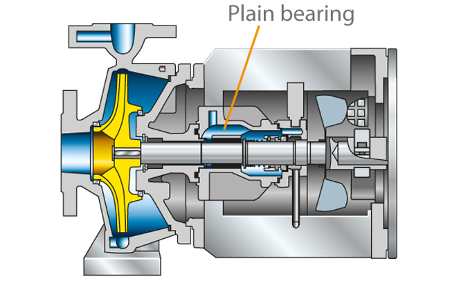
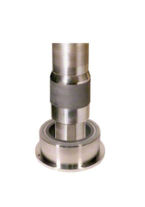
The plain bearing is an element frequently used in centrifugal pump construction that allows a moving component to slide within a stationary component. A distinction is made between radial plain bearings for radial forces (transverse forces) and axial (or thrust) plain bearings for axial forces (longitudinal forces). See Fig. 1 Plain bearing

This is an embedded image

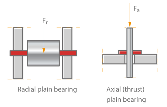
Radial plain bearing

On radial plain bearings, the moving part is the pin or journal of the axle or shaft; the stationary part is the bearing shell.

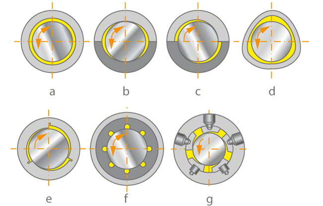
Bearing shells and other variants

  • a Cylindrical bearing shell
    see Fig. 2 a Plain bearing
  • b Two-face, lemon-bore bearing shell
    see Fig. 2 b Plain bearing
  • c Two-face, radially offset bearing shell
    see Fig. 2 c Plain bearing
  • d Three-face bearing shell
    See Fig. 2 d Plain bearing
  • e Three-face and multiple-face bearing shell with lubrication grooves or pockets
    see Fig. 2 e Plain bearing
  • f Rubber bearing
    see Fig. 2 f Plain bearing
  • g Multiple-face bearing with tilting radial pads
    see Fig. 2 g Plain bearing

This is an embedded image

This wide range of bearing designs is required to cater for the dynamic operating behaviour characteristic of centrifugal pump rotors. The vibration characteristics of rotors fitted with plain bearings depend largely on the rotor mass, the mass distribution, the shaft stiffness and the dampening characteristics of the bearings at a given load.

Appropriate rotor bearing design allows both types of lateral rotor vibrations (forced and self-induced) to be eliminated or reduced to an acceptable level for the machine. The dynamic bearing coefficients can be optimised. The choice of bearings is a key element of this optimisation, as each bearing offers different performance characteristics.
A bearing clearance is achieved through the appropriate sizing and mutual adjustment of both the moving and stationary bearing components.

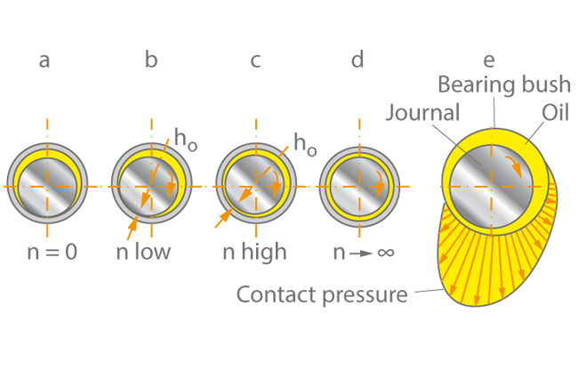
This is filled with a liquid or solid (grease type) lubricant in order to avoid sliding friction. When the bearing journal reaches a sufficient circumferential speed, the bearing clearance allows the lubricant to form a load-bearing wedge. The lubrication wedge separates the sliding faces from one another, meaning that the bearing is operating on full lubrication. This process is typical of hydrodynamic plain bearings.

Advantages and disadvantages of hydrodynamic plain bearings
Advantages:

  • Simple manufacture; the lubricant is fed either unpressurised or at very low feed pressure into the bearing during operation
  • Very little or no energy is required for the oil supply system

Disadvantages:

  • During start-up and run-down, full fluid film lubrication is impossible, resulting in wear on the running surfaces (mixed friction) see Fig. 4 Plain bearing

Another bearing type is the hydrostatic plain bearing. Here, the liquid lubricant is fed into the individual bearing pockets under high pressure

Forces are absorbed as a result of pressure differences:

  • High static pressure in the pockets on the loaded side of the running surface (small clearance during operation, therefore very small decrease in pressure in the lubricant layer)
  • Low static pressure in the pockets of the unloaded side of the running surface (large clearance during operation, therefore considerable pressure drop in the lubricant layer)

Advantages and disadvantages of hydrostatic plain bearings:

  • Advantage: full fluid film lubrication at all times, including start-up and run-down, therefore no excessive wear risk
  • Advantage: smaller dimensions and lower friction losses in comparison with hydrodynamic bearings of equal load-bearing capacity
  • Disadvantage: more expensive to manufacture than hydrodynamic plain bearings (several manufacturing operations)
  • Disadvantage: more expensive to operate because pressure boosting is required for the lubricant, leading to increased investment and energy costs

Hydrodynamic and hydrostatic types can be combined. In the case of plain bearings which operate hydrodynamically in the steady state, the increased friction during start-up and run-down and the wear associated with it can be reduced by providing auxiliary hydrostatic lubrication at a high pressure via longitudinal grooves which do not extend to the edge of the bearing shell.

The auxiliary lubricant feed is shut off during normal operation to ensure that the hydrodynamic pressure is maintained in the lubricating clearance gap.

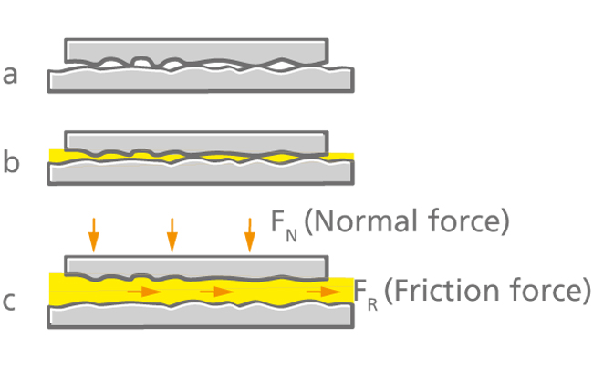
Friction conditions in a plain bearing
See Fig. 3 Plain bearing:

a. Dry friction:
     without a separating lubricant layer between the stationary and moving components

b. Mixed friction:
    a combination of dry and fluid friction

c. Fluid friction:
   with a separating lubricant layer (ideal situation)

This is an embedded image

This is an embedded image

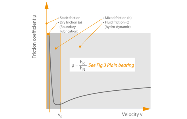
All three friction types can occur in hydrodynamic plain bearings during the three phases of operation: start-up, operation, run-down. Start-up is the operating phase from standstill to full operating speed. As the sliding velocity increases, hydrodynamic plain bearings experience mixed friction, with the amount of dry friction gradually giving way to fluid friction as speed increases further. Finally the transition point is reached when the surfaces separate from one another and full fluid film lubrication with a minimum of friction losses is established.

As the sliding velocity increases further, the thickness of the lubricant film also increases, but friction losses rise again slightly. See Fig. 5 Plain bearing

This is an embedded image

This frictional behaviour was the subject of research by Stribeck. See Fig. 4 Plain bearing

As a machine runs down, the plain bearings undergo the same process as described above for start-up, but in the reverse order (see Start-up process).

A plain bearing should generally have its steady-state operating point during the full fluid film lubrication phase. If mixed friction is present during continuous operation, excessive wear at the bearing faces can be expected. Particular care should be taken to correctly select and match the two materials whose surfaces require lubrication (wear, heat dissipation).

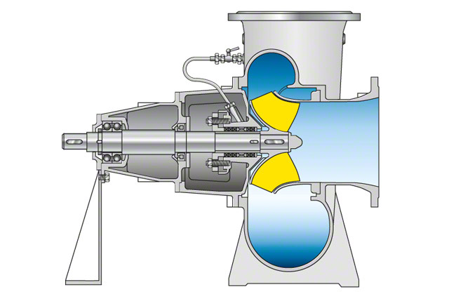
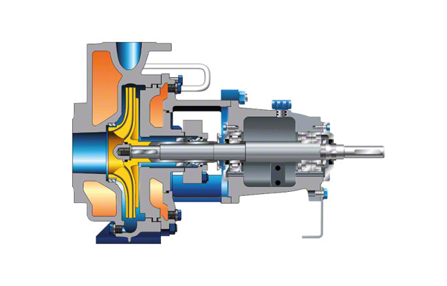
Many pumps are equipped with shaft guide bearings which are lubricated by the fluid handled. In these cases the choice of bearing materials is especially important as each fluid has its own characteristics as a lubricant. If clean water is used as a lubricant, several bearing materials with suitable tribological properties are available. These include metallic alloys, elastomers, hard rubber, electro-graphite with or without resin binders, hard graphite with or without resin binders or antimony impregnation.

If the fluid handled is used as a lubricant and is dirty or contains solids such as sand, the bearing materials should be made from hard metals or ceramic materials (e.g. silicon carbide). Using the same material for bearing bushes and shaft protecting sleeves results in a maintenance-free bearing.

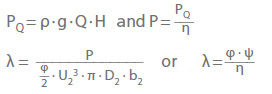
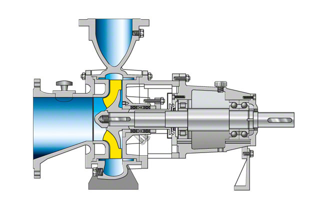
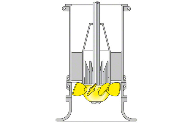
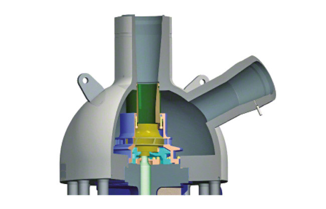
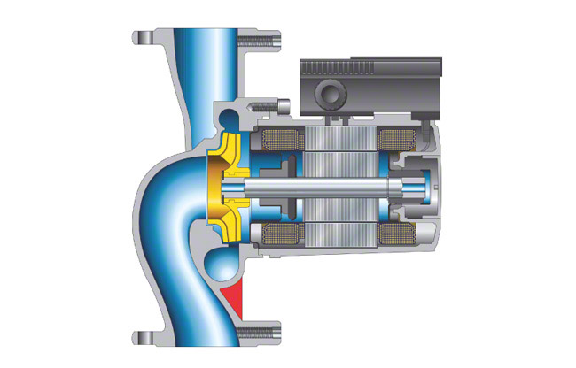
Fibre-reinforced ceramic bearings are being used more and more frequently due to their ability to resist tension and fractures. See Fig. 6 Plain bearing

This is an embedded image

Friction is converted into heat which is partly dissipated to the surrounding air via the bearing housing or the shaft. The plain bearing should therefore not exceed the max. bearing operating temperature. If necessary, a cooling system must be provided for the bearing or lubricant (usually water cooling).

The design of hydrodynamic plain bearings involves the solution of a complex problem which takes into account a number of factors such as bearing geometry and size, bearing load, the lubricant's viscosity the sliding velocity, the nature of the flow in the bearing (see Fluid mechanics) and the interaction between these factors.

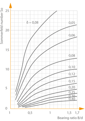
The objective of plain bearing design is to ensure that full fluid film lubrication can be reliably achieved during operation. The design process incorporates theoretical principles and experimental data, taking into account multiple interrelated characteristic coefficients (i.e. those relating to radial plain bearings): see Fig. 7 Plain bearing

This is an embedded image

This is an embedded image

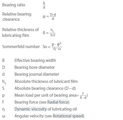
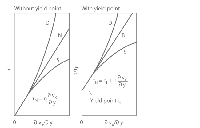
Plain bearings whose lubricant does not exhibit purely laminar flow characteristics (i.e. bearings with very high speeds and simultaneously very low lubricant viscosities tend to have a higher load-bearing capacity, but also higher friction losses. Here, the qualitative difference between a laminar and a turbulent flow plays a decisive role, alongside the characteristic coefficients for plain bearings already mentioned. Designing plain bearings with turbulent lubricant flow is much more complicated than designing bearings with laminar lubricant flow.

Axial (thrust) plain bearing

The moving part of an axial (thrust) plain bearing is the thrust collar or plate.

Stationary part and its variants
See Fig. 8 Plain bearing:
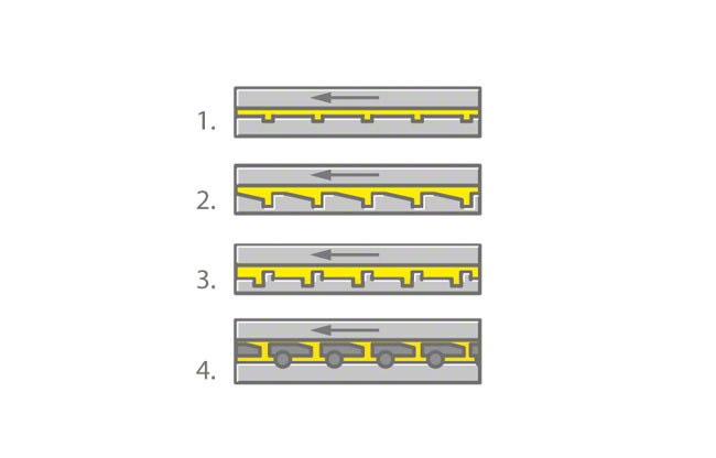
This is an embedded image

  1. Thrust bearing ring
  2. Thrust bearing ring with machined wedge faces
  3. Thrust bearing ring with stepped damming gap
  4. Eccentrically supported tilting pads or often centrally supported tilting pads (e.g. where a cooling water pump has to rotate in reverse (turbine mode) because of a backflow from the piping)

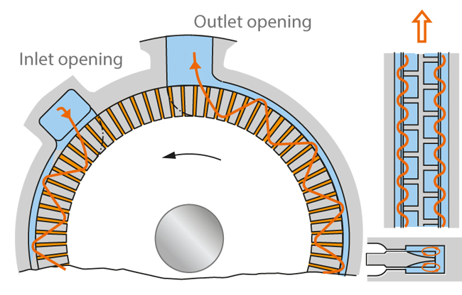
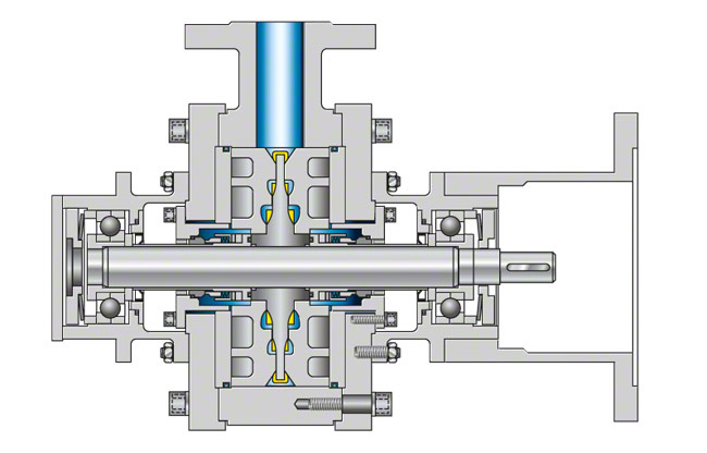
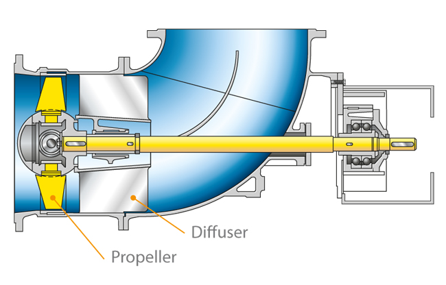
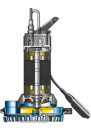
Depending on the design axial (thrust) plain bearings are subdivided into hydrodynamic, hydrostatic and combined hydrostatic-hydrodynamic plain bearings for special applications. Both basic design types must allow sufficient axial shaft movement to accommodate the lubricant film thickness, which varies according to load, viscosity of the lubricant, and sliding velocity. The same arguments as for radial plain bearings apply to the advantages and disadvantages of hydrodynamic versus hydrostatic axial (thrust) plain bearings. Fig. 9 Plain bearing illustrates a product-lubricated carbon bearing in a circulating pump.

This is an embedded image


Plastomer

A plastomer is a type of plastic that becomes flexible beyond a specific temperature, but which returns to its original state once it has cooled down again. This process can be repeated as often as required, provided that the plastic is not overheated.

PLC

PLC stands for "Programmable Logic Controller" and refers to a computer-based control unit used for the (electronical) open-loop or closed-loop control of machines and systems. Functionality is determined by an application that is relatively easy to create using standardised programming languages. The sensors and actuators are connected to this assembly in analog or (increasingly) digital fashion via a data bus (see Bus) to minimise wiring outlay.

A PLC processes the sensor signals, calculates the responses required, and controls the actuators in cyclical programs while the application indicates the current status of the sensors so that the user can control the actuators in line with requirements and achieve the desired results.

PM-Motor

The PM in "PM motor" stands for "permanent magnet" and refers to the fact that this motor is electronically commutated (EC motor) and has a rotor comprising a permanent magnet.

PN

ISO 7268 or EN 1333 defines PN as an alpha-numeric designation which is used for reference purposes and relates the mechanical and dimensional properties of a piping system component.

The letters PN are followed by a dimensionless number (e.g. PN16). The figure followed by the letters PN does not represent a directly measurable value and should not be used in calculations unless this has been specified in the relevant standards.

Components with the same PN (e.g. flanges) and the same DN have identical mating dimensions. Other designations such as class are also common but should only be used in combination with the specification NPS (Nominal Pipe Size).

The standardised nominal pressure classes defined in the obsolete DIN 2401 have not been included in the EN 1333 standard. See Fig. 1 PN

This is an embedded image

Regardless of these provisions, the nominal pressure classes specified in the obsolete DIN 2401 are still applied and are therefore listed for information.
See Fig. 2 PN

This is an embedded image


Positive displacement pump

Positive displacement pump is a collective term for all pumps operating according to the positive displacement principle. These pumps are also referred to as volumetric pumps as they pump the fluid handled in an enclosed volume. Displacement bodies periodically increase and decrease the working volumes, thus transferring energy to the fluid handled. The working volumes are separated from the inlet and discharge by separating elements. In the case of reciprocating positive displacement pumps (see Fig.1 Positive displacement pump) the separating elements are lift check valves or swing check valves which are automatically controlled by pressure differences, or, for higher rotational speeds gate valves actuated by a crank mechanism. These valves prevent the fluid handled from flowing back into the suction line  or discharge line. In the case of rotary positive displacement pumps, controlled gap seals changing with the rotating movement of the displacement bodies serve as separating elements. The function of all separating elements is to control the inlet and outlet of the fluid to and from the working volume at the right time in order to create a flow (see Flow rate) by means of alternate intake and displacement via the displacement body according to the corresponding design principle. The head is independent of the pump speed.

A distinction is made between fixed and variable volume displacement (fixed and variable displacement pumps). The pumps are further distinguished by the motion of their displacement bodies, which can be reciprocating (moving to and fro) or rotary. The reciprocating motion can be either linear (e.g. piston or diaphragm pump) or crescent-shaped (e.g. reciprocating vane pump). Examples of rotary positive displacement pumps are gear pumps, screw pumps, progressive cavity pumps, rotary piston pumps, water ring pumps, rotary vane pumps, roller vane pumps and peristaltic pumps.

The most commonly known positive displacement pumps are piston pumps / plunger pumps. Their displacement body, e.g. a plunger, describes a linear motion. See Fig. 1 Positive displacement pump

In double-acting displacement pumps two working volumes are arranged opposite each other and use the same displacement bodies, which leads to a more even torque curve and flow rate.

Pulsations in the flow can further be absorbed by air vessels (accumulators) acting as short-term storage vessels in the suction line and discharge line or by several cylinders arranged in parallel with a common crankshaft (e.g. duplex or triplex pump). The cylinders can be arranged horizontally or vertically. The crankshaft is usually fitted in a horizontal position. See Fig.1 Positive displacement pump

Positive displacement pumps are primarily used in systems requiring pressurised water and oil (pressure pump) in the chemical industry (e.g. dosing pump) and frequently also on board vessels and in small and medium-sized industrial plants.

Large quantities of positive displacement pumps are employed by the automotive industry as injection pumps for diesel engines. In drive systems positive displacement pumps are widely used as radial and axial piston or plunger pumps for continuously variable energy transmission.

This is an embedded image


Potential equalisation

Potential equalisation refers to the electrical connection that all but equalises conductive bodies (e.g. casing, housings, mounting plates, etc.), electrical operating equipment, and foreign, conductive parts with earth potential. A protective measure, potential equalisation ensures that the contact voltage encountered during a fault is very minimal and cannot cause accidents. Potential equalisation must be compatible with high frequencies and low resistance. Equipotential bonding strips also serve as an earth reference point for electronic open-loop control systems.

Potential flow

The term potential flow designates (apart from isolated singularities) a vortex-free and source-free flow. Its velocity field v fulfils the condition of being irrotational rot(v) = o and can be derived in accordance with v = grad(Φ) from a velocity potential (Φ).

In the case of incompressible media, the velocity potential Φ satisfies the potential equation ΔΦ = 0, where, Δ is the Laplace operator. The potential equation can verify the condition of tangential flow direction at solid walls, but not no-slip conditions. In a potential flow, a closed body surrounded by flow on all sides does not experience drag, only lift.

Simple examples of potential flow are parallel, source or sink flow and the potential vortex. In a source or sink flow, the radial component (vr) (which is the only flow component present) varies inversely with the radial distance (r) from the centre; in a potential vortex, the same applies for the tangential component (vu) of the velocity (again, the only component present). Both flows feature a singularity at the centre where r = 0, as here the velocity becomes infinite.

Strictly speaking, potential flows can only be flows of frictionless fluids. However, flows of real fluids subject to friction can be treated as approximating potential flows at sufficiently large distances from solid walls, while friction forces need only be taken into account in a thin boundary layer close to the wall.

If the body contour is increased in the calculation by the displacement thickness of the boundary layer and the Reynolds number is high (i.e. for thin boundary layers), the flow around bodies – in particular the flow and pressure distribution in a vane cascade – can be calculated reasonably accurately as a potential flow.

Important methods of calculating a potential flow (e.g. aerofoil theory) include the conformal representation, or conformal mapping, function (by which a flow field is transformed from one complex plane into another preserving angles) or the singularity method (by which the flow field is represented by superimposing separate or continuous singularities such as sources, sinks, vortices on the body surrounded by the flow).

Numerical flow simulation methods also allow a potential flow to be directly calculated on the basis of the differential equations describing the flow field (Euler's equations). In contrast to Navier-Stokes equations, these equations do not include the friction term. When considering the potential flow in a rotating vane cascade, it must be taken into account that although the absolute flow (v) is irrotational, the rigid body reference system prevents this condition for the relative flow (w), meaning that rot(w) does not equal zero. As a result, a so-called relative vortex rotating in the opposite direction to the rotation of the impeller develops in the vane channel of an impeller through which a frictionless flow passes.

Note: All arrows () mark vector quantities. For technical reasons, it is not possible to display them correctly above the letters.

Power factor

The power factor or cos φ as applied to electrical engineering describes the relationship between effective power Pe and apparent power Pa with respect to AC circuits. 

This is an embedded image

Apparent power is the product of a phase shift between voltage and current. Inductive and capacitive resistors in AC circuits effect a shift in the current curve with respect to voltage. This shift is described by angle φ.

The phase shift between voltage and current is + 90 degrees for capacitance and - 90 degrees for inductance. Phase shifts do not occur with ohmic resistance. Mixed resistance refers to impedance, whose phase displacement angles lie between 0 degrees and + 90 degrees and 0 degrees and – 90 degrees.

The power factor for pure sinusoidal current and voltage is equivalent to the cosine of the phase displacement angle (φ). It is used to calculate the effective current (Ie) and effective power (Pe):

This is an embedded image

Power companies frequently require a minimum power factor of 0.9 from customers. When this value is undershot, the reactive energy consumed is invoiced separately. Reactive power compensation systems can be used to increase the power factor:

This is an embedded image


Power input

The power input of a centrifugal pump (pump input power) is the mechanical power taken by the pump shaft or coupling from the drive. The SI unit of measurement for power input is watts (W). Input power

This is an embedded image

Calculation must be based on the flow rate (Q) at the inlet cross-section of the centrifugal pump if the fluid handled exhibits substantial compressibility. Pump input power can also be defined more precisely in conjunction with centrifugal pumps.

Special terms pertaining to pump input power

  • Optimum pump input power (Popt): power input at the operating point of best efficiency 
  • Maximum pump input power (PG): highest pump input power of the operating range as defined in the delivery contract
  • Zero-flow pump input power (P0):
    Pump input power when Q = 0 m3/s (see Characteristic curve)


Power loss

Power loss (Pv) is the difference between the input and output power of a device, apparatus, pump set, or process. With electrical and electronic devices, as well as pumps, apparatuses and processes, this undesirable loss is converted into heat (see Head, Efficiency). 

Power loss arises when transferring electrical energy via cables, for example.

The loss of power when transferring electrical energy depends directly on the line resistance (R) and, consequently, on the line diameter, as well as on the material used and the electric current flowing (I). It can be calculated by dividing the voltage drop by the line resistance R (U):

This is an embedded image

Particularly when transferring and converting energy, power loss should be considered as a loss that should be minimised, as is the case with gear units (mechanical energy), transformers (electrical energy), motors (conversion of electrical to mechanical energy), and pumps (conversion of mechanical to hydraulic energy). The resulting lost heat is dissipated by means of radiation, heat transfer, or convection (cooler).

Power measurement

Electrical power measurement is a method of measuring the power in a circuit, which is expressed in watts. In centrifugal pump applications, electrical power is measured using electrical and mechanical-electrical methods.

Measurement of electrical power for:

  • Direct current: voltage (V) and current (I) measured using voltmeters and ammeters
  • Single-phase alternating current: effective power (Peff) measured using a wattmeter
  • Three-phase current: two power values (Peff1 and Peff2) measured using two wattmeters (dual wattmeter method), with total electrical power calculated as
    Peff = Peff1 + Peff2. See Fig. 1 Power measurement

This is an embedded image

These measurement functions can often be combined in a single (electronic) measuring instrument with an easy-to-read display. This dual watt-meter method can always be applied, even for an inaccessible neutral conductor, phase imbalance, or fluctuating power. If the neutral conductor is accessible (motor with star configuration) and the phases are balanced, a single power value (Peff1) can be measured to determine the total electrical power using the formula Peff = 3 ∙ Peff1.
See Fig. 2 Power measurement.

This is an embedded image

The efficiency of the motor (ηM), and possibly of the gearing, must be known to determine the power output.
To rule out uncertainties in motor and gear efficiency for frequency-controlled drives in particular, a torque and speed-measuring instrument is installed in the drive train before the pump, especially during testing in a test bay.

Instruments for measuring the power input of a pump during testing in a test bay:

  • Hub-type torque meter, see Fig. 3 Power measurement

This is an embedded image

  • Disc-type torque meter, see Fig. 4 Power measurement

This is an embedded image

These instruments are installed between the motor and pump or between the gear and pump as part of the coupling or as a separate instrument. Rotational speed is generally also supported and measured.

Different systems, the majority of which are electronic, are available for transferring the signals. The main challenge with this technology is to reliably transfer the measuring signal from the rotating to the stationary system and to supply power to the measuring elements. Initially, slip rings were used for this purpose. However, they are very susceptible to malfunctions, which is why they have been replaced with contact-free transmission devices in precision systems. The latter transmit and display the measuring signals in the form of amplitude or frequency modulations, depending on the system.

PRANDTL tube

The PRANDTL tube is a dynamic pressure sensor for measuring the local velocity in a flow and is used in metrology applications.  

Local flow velocity is determined by quantifying the difference between the total pressure (measured as with the pitot tube) and static pressure (measured at holes in the sides of the PRANDTL tube).

Pre-swirl control

Pre-swirl control allows a change in pump head. This requires the installation of a diffuser with variable pitch diffuser vanes upstream of an impeller. Usually diffusers with variable pitch vanes are only used on centrifugal pumps for pre-swirl control purposes.

The control range is broadened with increasing specific speed, thus limiting the use of these devices to mixed flow and axial flow impellers.

Compared with other types of control, both the effort required and the associated costs are relatively low.

Pressure

Pressure is a physical property and specifies the force exerted on a certain unit area. Its symbol is p and unit is Pa (Pascal); however N/m² and bar (fluid) are also commonly used.

In fluid systems, the values and terms defined for pressure are as laid down in DIN 24312 (as an extension of ISO 2944). It is necessary to distinguish between static and dynamic pressure.

Static pressure

Static pressure is pressure which a probe entrained with the fluid would measure (see Pressure measurement).In centrifugal pump technology, the term pressure always refers to a static pressure. In accordance with DIN EN ISO 17769-1, the barometric pressure (pb) and the vapour pressure (pD) of the fluid handled must be specified as absolute pressure, whereas all others must be specified as gauge pressures
(e.g. in relation to barometric pressure). In the case of pressures below atmospheric, the values will be negative ones.

Overview of the most frequently used static pressures 
see Fig. 2 Head

  • Pressure at inlet cross-section of the pump (ps). Gauge pressure at its elevation (zs)
  • Pressure at outlet cross-section of the pump (pd). Gauge pressure at its elevation (zd)
  • Pressure in the pressure gauge at the inlet cross-section of the pump (ps,PG). Gauge pressure in the pressure gauge

if the measuring line is filled with liquid:

ps = psM + ρ  g  zs,M

ρ          Density of the fluid in the measuring line
g          Acceleration due to gravity
zs,PG       Difference between the elevations of the pressure gauge middle and the point of measurement at the inlet cross-section of the pump

in an air-filled measuring line:
ps = psM

This also applies to the pressure in the pressure gauge at the pump's outlet cross-section (pdPG).

  • Pressure at inlet cross-section of the system (ps).
    Gauge pressure at the inlet cross-section (As) at its elevation (zs), i.e. if there is a liquid level present, the gauge pressure at this liquid level
  • Pressure at outlet cross-section of the system (pd).
    Gauge pressure at the outlet cross-section (Ad) at its elevation (zd), i.e. if there is a liquid level present, the gauge pressure at this liquid level
  • Barometric pressure at pump installation (pb). (See Atmospheric pressure
  • Vapour pressure (vapourisation pressure) of the fluid handled (pV). Absolute pressure at which the fluid handled evaporates at the temperature prevailing at the inlet cross-section of the pump.

Dynamic pressure 
Dynamic pressure at a stagnation point corresponds precisely to the increase in static pressure along the stream line (see stream line) as a result of the fluid being brought there to rest.

It is therefore also known as "stagnation pressure".

This is an embedded image

This results in the total pressure (ptot):

This is an embedded image

Pressure booster system

If the standard pressure of an existing water supply system is unable to ensure supply to consumers located at higher elevations, e.g. in high-rise buildings or elevated residential areas, it is necessary to boost the water pressure. This is accomplished by installing one or more booster pumps in a bypass line to the main water supply pipe.

In order to prevent any pumping in a closed circuit, a check valve (see Valve) is fitted in the main water supply pipe between the booster pumps' suction and discharge connections. See Fig. 1 Pressure booster system

This is an embedded image

Modern pressure booster systems are operated with variable speed pumps. See Fig. 2 Pressure booster system

This is an embedded image

These may also be arranged in parallel which offers the additional benefit of a wide control range. Large fluctuations in pressure upstream of the pump (inlet pressure) can be well controlled, and the pressure booster systems' variable speed pumps make them very efficient. The installation of pressure controllers/reducers can be completely dispensed with which, in turn, means that continuous pressure losses are avoided. These systems are unparalleled in terms of user convenience and operational reliability.

As the discharge pressure is virtually constant, it is only necessary that the head actually required be adjusted to match the respective inlet pressure.

This means that the pressure fluctuations/surge pressures experienced with other systems when pressure boosting pumps cut in or out are no longer felt by the user (no change in temperature when taking a shower, etc.). In addition, the system's operating noises are markedly reduced, at least when it is predominantly operated in the low flow range. If one variable speed pump fails, this does not result in pressure fluctuations or unstable operation, i.e. hunting (excessively frequent pump starting/stopping).


Normally these types of pressure booster systems also eliminate the need for pressure vessels (membrane-type accumulators) which present hygienic problems. The control and monitoring algorithms generally in use today allow zero demand (flow rate demand = 0) to be quickly and reliably identified, ensuring prompt pump shutdown and avoiding unnecessary (drinking) water heating. See Fig. 2 Pressure booster system

The relatively high expenditure for closed-loop control systems justifies the application of micro-processors. Standardised package units incorporate all the components necessary for automatic operation and can be connected with a minimum of installation work.


HyaDuo 2 D FL Compact

Pressure class

Pressure classes are nominal pressure ratings classified in line with the ISO 7268 preferred number series (see PN). They represent the basis for the specifications made in piping component standards.

Pressure drop

Pressure drop is defined both as a rapid reduction in pressure in a space, e.g. in a tank, and as a drop in pressure between two locations or cross-sections along a stream line, e.g. in piping.

Pressure exchanger

Pressure exchangers can be used in place of conventional turbine solutions for energy recovery in RO (reverse osmosis) seawater desalination plants.

The pressure exchanger transfers the hydraulic energy in the brine directly to the incoming seawater, referred to as feedwater (see also seawater desalination plant).
See Fig. 1 Pressure exchanger

Operating principle with two pressure vessels

  • The pressure exchanger comprises two pressure vessels which are operated simultaneously. The check valve unit is installed at one end of the pressure vessels and the rotary valve at the other. See Fig. 2 Pressure exchanger
  • The rotary valve is connected to the plant piping through which the brine flows. The check valve unit is connected to the feedwater piping. Each side is equipped
  • with one high-pressure and one low-pressure pipe for the seawater and the brine.
  • The pressure exchanger is operated in cycles, with each cycle being defined by a 180° rotation of the rotary valve. Each cycle has a low-pressure phase in which the fluid flows from the check valve unit to the rotary valve and a high-pressure phase in which the fluid flows from the rotary valve to the check valve unit. The pressure vessels are filled with seawater in the low-pressure phase, in the high-pressure phase the seawater is pumped into the plant.
  • The rotary valve is driven by a servomotor (gearbox). Actuating the valve changes the pressure in the vessels and the flow's direction. As the pressure vessels operate alternately, one conveys low-pressure fluid and the other high-pressure fluid. The fluids in the vessels always flow in opposing directions. Each pressure vessel may be equipped with a piston separating the fluids (seawater and brine).
  • Pressures of between 50 and 80 bar are required to desalinate seawater. A high-pressure pump provides the inlet pressure required for the reverse osmosis process. Concentrated brine resulting from this process leaves the membrane modules under high pressure and flows through a pressure exchanger where this pressure is transferred directly to the incoming seawater (feedwater). A recirculation pump then pumps the feedwater to the membranes.
  • The pressure exchanger's control unit records and processes all operating conditions in the higher-level reverse osmosis (RO) system in order to optimise operation. It ensures that the water columns in the pressure exchanger vessels are accelerated and decelerated so gently that actuating the rotary valves of the pressure exchanger does not cause pulsations.
  • All components including high-pressure and recirculation pumps are made from seawater-resistant materials.

This is an embedded image


Pressure head

The pressure head describes the measure for a liquid's pressure and is expressed by:

This is an embedded image

p    Static pressure
ρ    Density of fluid handled
g    Acceleration due to gravity

According to EN 12723, pressure head is the pressure energy in a fluid under static pressure (p) per unit weight. Pressure head is expressed in metres (m).

Alongside the velocity head and the geodetic height, the pressure head is a component in Bernoulli's equation (see Fluid mechanics) used to calculate the total head.

Pressure loss

Pressure loss (pL) is a pressure difference caused by wall friction (in pipes) and resistances (in valves, fittings etc.). It is calculated on the basis of the head loss (HL) which is independent of the density (ρ), using the following equation:

This is an embedded image

ρ    Density in kg/m³
g    Acceleration due to gravity (9.81 m/s²)
HL  Head loss in m
pL  Pressure loss in Pa (1 bar = 100,000 Pa)

Pressure measurement

Pressure measurement refers to the process of determining the physical pressure of fluids and involves using a pressure measuring instrument such as a pressure gauge to determine and display data (also see Metrology).

Fluid columns are used in the most basic form of pressure measurement.
See Fig. 1 Pressure measurement

This is an embedded image

Spring pressure gauges are used for higher pressures. See Fig. 2 Pressure measurement

This is an embedded image

Pressure gauges are also frequently fitted with sensors, e.g. differential pressure or over-pressure sensors, which use capacitive, inductive, or piezoelectric sensing, or high-resolution sensing for transient pressure fields.

Preventive maintenance

Preventive maintenance is a process whereby suitable sensors are used to determine the level of wear on a component by analysing the cumulated measured values with special software. This makes it possible to identify the optimal time for maintenance, which can then be entered into an electronic maintenance schedule.


Priming

Das Auffüllen der Saugleitung mit Flüssigkeit muss bei einer nicht selbstansaugenden Kreiselpumpe vor dem Anlaufvorgang (siehe Pumpenanlage) erfolgen. Ist das Sauglaufrad bei Stillstand nicht überflutet, kann ein Fußventil oder eine Rückschlagklappe unterhalb des niedrigsten Wasserspiegels in der Saugleitung angeordnet werden.

Principle of conservation of momentum

The principle of conservation of momentum or momentum theorem is a conservation law which states that all external forces acting on a fluid contained in an isolated environment (control volume) must be in equilibrium. It plays an important role in centrifugal pump engineering (see also Fluid mechanics). The principle of conservation of momentum represents the integral form of the Navier-Stokes equation.

Process control system

Process control systems monitor and control automated plants and assume such core tasks as recording process data, evaluating, visualising, and operating/controlling processes as well as alerting, logging, and balancing.

Process pump

The process pump is a centrifugal pump which is used in chemical processes, e.g. in oil refineries and the petrochemical industry (see Refinery pump). Its design is generally of the back pull-out type. Like chemical pumps, process pumps are used for handling aggressive chemical fluids.

They are also suitable for high system pressures and temperatures. If a process pump is used in the oil industry, it must generally comply with the requirements of the American Petroleum Institute (API).

PROFIBUS

The term PROFIBUS stands for "PROcess FIeldBUS" and is a universal, open field bus system. This serial communications system is used to exchange information between automation systems and connected decentralised field devices.

Progressive cavity pump

Progressive cavity pumps, also known as helical rotor pumps, are rotating positive displacement pumps. The displacement element, which also seals off the cavities, is a helical rotor. It rotates eccentrically in a casing with a double helix and an oval cross-section.

Propeller pump

A common feature of a ship's propeller, a propeller-type mixer and a propeller pump is the axial flow impeller (see Axial flow pump and Propeller). 

Propellers can be designed with fixed-pitch blades (fixed-pitch propeller), blades whose pitch can only be adjusted with the propeller dismantled (adjustable-pitch propeller) or blades whose pitch can be adjusted during operation (variable-pitch propeller). For this reason a pump with adjustable vanes in a mixed flow impeller is also referred to as a propeller pump.

Of all centrifugal pumps, propeller pumps have the highest specific speeds (ns > 110 rpm) but are used most commonly for ns > 160 rpm. The higher the specific speed, the smaller the number of impeller blades, the less pronounced the profile convexity and the smaller the hub-to-tip ratio.

Propeller pumps are suitable for large flow rates and low heads (up to approximately 15 m in a stage with an axial flow propeller and 20 m in a stage with a mixed flow impeller).

Their H/Q curve is steep compared to that of other centrifugal pumps; the cut-off point marks the operating behaviour of this pump type. See Figs. 3, 4 Characteristic curves selection chart and Figs. 1, 4 Characteristic curve

The power input curve (see Characteristic curve) reaches its maximum at zero flow, which is why propeller pumps are started up against an open discharge-side gate valve to prevent overloading of the drive (during the start-up process). The typical characteristic curve (with a "saddle" and "cut-off point" and with the power input increasing as flow rate decreases) makes considering the otherwise uneconomical bypass adjustment worthwhile as a control option: Opening of a bypass line reduces the power input and head while increasing the effective flow rate.

The impeller blade pitch and with that the volume flow rate and "cut-off point" can be adjusted during operation using mechanical, electric or hydraulic adjustment gear (see Impeller blade pitch control). This type of control is very commonly used for propeller pumps. Blade pitch adjustment with the propeller dismantled can be used for altering the head without having to fit any new components or re-machine fitted components. Variable-pitch propeller pumps are started up at minimum pitch angles, i.e. minimum power input.

Axial flow propeller pumps (see Fig. 1 Pump casing) are commonly designed as tubular casing pumps mixed flow propeller pumps can either be tubular casing pumps or volute casing pumps (with a concrete casing for large pump sizes).

In tubular casing pumps the pump shaft is usually supported by water-lubricated shaft guide bearings (see Plain bearing) in the column pipe. The axial thrust is absorbed by a sturdy axial bearing (see Plain bearing and Rolling element bearing) installed above the gland packing. See Fig. 1 Propeller pump

This is an embedded image

Since the flow in axial flow impellers is very sensitive to disturbances in the approach flow, particular attention must be paid to the design and implementation of the intake chambers, bellmouths or intake elbows (see Inlet conditions). 

Propeller pumps can be several metres in diameter.

Propeller pumps are usually designed with a single stage; for higher heads axial multistage propeller pumps are employed in individual cases, making use of impeller blade pitch control. Compared to single-stage axial flow pumps, the costs are considerably higher for multistage variable pitch propeller pumps or propeller pumps with a rotating assembly which can be pulled out (see Pump in pull-out design).

If higher heads are required, the more common alternative is to adopt a propeller pump with a mixed flow impeller (see Propeller) or a mixed flow pump. In this case, the impeller vanes (blades) of the propeller pump face in the direction opposing the main flow; their adjustable axes are set to an angle of 25º to 45º against the radial direction. A propeller pump with mixed flow propeller blades combines the advantages of the high heads of mixed flow impellers with the good control capabilities of variable pitch propellers.

Propeller pumps are employed as land reclamation pumps (see Pumps for use in low-lift pumping stations) (drainage and irrigation), as cooling water pumps (power stations, on board vessels), as circulating pumps (boiling water reactor, heating system), as universal elbow casing pumps (in the chemical and food processing industries) as well as for generating thrust with a propeller in a transverse thruster. See Fig. 2 Propeller pump

This is an embedded image


Protective earth conductor

Earth conductors are also referred to as earth or earth lines and are designated by the letters PE, which stand for "Protective Earth". They also have the green-and-yellow colour combination, whereby both colours are reserved for this conductor type, and offer protective earthing for people and animals as well as electrical installations.

Earth conductors in electrical installations are fitted such that the outer metallic housing is connected to the earth. If, in the event of a fault, the supply voltage can reach the outside parts of an electrical piece of operating equipment, the equipment must be disconnected from the voltage immediately. This occurs via residual current devices or overcurrent protective devices (e.g. fuse), depending on the type of supply. The time required for deactivation is between 0.1 and 5 seconds in line with the severity of the situation.

Protective earthing

Protective earthing is a type of earthing, that is used to protect people and animals from electric shocks and is only effective in the event of a fault.

The conductive parts of a piece of electric operating equipment or installation that are not associated with the operating circuit are immediately earthed by an earth conductor to prevent excessive contact voltage.

Protective layer

According to DIN 50 902 a protective layer (also coating) is a cover consisting of one or several layers on the base material. It may either be formed by coating or by change of the surface material composition (cf. DIN 8580). Possible protective layers include surface, passive and diffusion layers, or protective layers formed by lime and rust. 

Surface layer

  • This is a layer of solid reaction products formed by corrosion which covers the surface more or less uniformly. It allows slowing down corrosion processes.
  • If the surface layer forms unevenly, corrosion cells may develop.
  • A surface layer is only regarded as a protective layer if it is uniformly developed and slows down corrosion substantially. See Fig. 1 Protective layer

Passive layer

  • This is a protective layer created by corrosion often not detectable by an optical microscope. It renders the metal "passive" to its environment (see DIN EN ISO 8044).
  • The best-known passive layers are those on stainless steels, aluminium and titanium.

Diffusion layer

  • A diffusion layer is a layer formed when a metal or non-metal diffuses into the base material. 

Lime-rust protective layer

  • The formation of a lime-rust protective layer depends on factors such as pH value, oxygen content, salt content, temperature, flow velocitywater hardness etc.
  • All naturally occurring water contains carbonic acid, both in its free form and in the form of anions. The chemically bound form is found as either calcium carbonate or magnesium carbonate.
  • The free carbon dioxide (CO2) is mostly found as dissolved gas. The free carbonic acid ensures that the hydrogen carbonates are held in solution according to the lime-carbonic acid equilibrium.

This is an embedded image

  • The portion of free carbonic acid contained in water in excess of the concentration of associated free carbonic acid is called excess or aggressive carbonic acid.
  • Only waters which do not contain excess free carbonic acid may form surface layers on metals. With regard to unalloyed steel, this means that after initial rust attacks corrosion is considerably reduced due to the lime-rust protective layer (e.g. limescale).

This is an embedded image


PTC resistor

The PTC (Positive Temperature Coefficient) resistor is also referred to as the PTC thermistor and is a thermistor with a positive temperature coefficient. Its resistance value also increases as temperature increases.

A PTC resistor is used to measure temperature, especially in the context of ensuring thermal overload protection for electric motors.

Pulp consistency

Pulp consistency should not be confused with the density of fluids handled and is extremely important in pulp pumping.

 A measure of the pulp consistency is given by the percentage by weight of dry substances, a distinction being made between air-dry (% A.D.) and bone-dry (% B.D.).

The German Wood Pulp Manufacturers' Association has laid down a standard moisture content of 12 %. Air-dry pulp therefore contains 88 % of dry solids. A pulp consistency of x % of air-dry pulp therefore corresponds to a pulp consistency of 0.88 · x % bone-dry.

It is usual in the cellulose industry to specify the pulp content in a grams/weight percentage of a 1 kg mixture of pulp and water. This means, for example, that a pulp suspension (mixture of pulp and water) of 30 g bone-dry corresponds to a pulp consistency of 3 % bone-dry. Centrifugal pumps are used for the pumping of pulp suspensions up to pulp consistencies of approximately 7 % bone-dry. This corresponds to a content of 70 kg bone-dry pulp (100 % dry solids) in one tonne of pulp/water mixture.

Pulp suspensions with a pulp consistency up to 1 % bone-dry approx. can be considered as pure water as far as their flow characteristics are concerned, in respect of the design of the pumps, valves and piping required to handle them. A very clear picture of the behaviour of higher pulp consistencies can be obtained from the pouring test as a function of the angle of tilt of the container. See Fig. 1 Pulp consistency 

Pulp consistencies of up to 3 % bone-dry approx. can be handled by means of conventional centrifugal pumps. Within the region ranging from approx. 3 % to a maximum of approx. 6 % bone-dry, slurry pumps must be used.

This is an embedded image


Pulp pump

Pulp pumps are used for transporting mixtures of liquid and solid components (e.g. fibrous materials in the pulp and paper industry).

Pulp pumps are usually horizontal, single-flow, single-entry centrifugal pumps in back pull-out design, They are especially designed for handling fluids with non-NEWTONian flow properties (see NEWTONian liquid) as well as the high air contents of pulps (see Pulp pumping). See Fig. 1 Pulp pump

This is an embedded image

Large inspection holes facilitate a quick and easy removal of any clogging. Special impeller types are fitted which match the type of pulp and the pump application. These include open impellers, which can be combined with a side channel impeller if the pulp is hard to pump, and free-flow impellers (also see Torque flow pump). 

Free-flow impellers are used if the pulps to be pumped (also see Pulp pumping) are contaminated or if the mixing effect of the free-flow impeller creating a vortex is advantageous for a particular process.

A wear plate, which is easy to replace, protects the pump casing against wear on the suction side. The pump shaft is protected against corrosion and wear at the wetted end by means of a shaft seal which prevents the shaft from any contact with the fluid pumped. The shaft seal is either a gland packing or a mechanical seal, both of which are supplied with a barrier fluid.

Pulp pumping

Pulp pumping refers to the transportation of pulp suspensions of various pulp consistencies and types (e.g. fibrous material or slurries) by means of conventional centrifugal or pulp pumps in the cellulose and paper industry.

Pulp types

Cellulose is an important raw material for the manufacture of paper, artificial silk (rayon), rayon staple (synthetic wool) and nitrocellulose.

Depending on the base product, cellulose is subdivided into wood pulp from leaf woods (hardwoods) and pine woods (soft woods), straw pulp and other types of cellulose which originate from various raw material sources such as bagasse (sugar cane waste after crushing), reeds or bamboo cane. Cellulose is also classed as either sulphate cellulose or sulphite cellulose according to the chemical treatment process it undergoes.

Wood pulp, also known as mechanical wood pulp, is prepared mechanically by grinding down decorticated hardwood or soft wood. Wood pulp is an important base product for the manufacture of paper and cardboard (paper pulp or stock).

Flow behaviour 

In contrast to solids transport, where a distinction between the solid matter and the carrier liquid is possible, the suspensions created when cellulose and paper industry pulp floats in water exhibit specific flow behaviour which must be taken into account when designing (see Design point) pumps to handle them. This behaviour depends on both the pulp type (base product, treatment processes, admixtures) and pulp consistency.

Viscous liquids are classified as follows according to their flow behaviour: when the shear stress is proportional to the velocity gradient (∂vx/∂y), the liquid in question is a Newtonian or normal viscosity liquid to which the laws of fluid mechanics apply. All other types of liquids are referred
to as abnormal viscosity or non-Newtonian liquids; their fluid dynamics are the focus of rheology.

Pulp pumping also deals with these fluids; they are categorised according to their shear behaviour where deformation depends on the magnitude, variation or duration of forces acting upon them. See Fig. 1 Pulp pumping

This is an embedded image

Flow behaviour of abnormal viscosity fluids

  • Bingham plastic (e.g. paste): shear stress has a finite yield point.
  • Dilatant fluid (e.g. PVC): shear stress increases progressively in relation to the velocity gradient, but independent of time.
  • Shear thinning or pseudoplastic fluids (e.g. biogas, liquid rubber):
    shear stress increases digressively in relation to the velocity gradient, but independent of time
  • Rheopectic fluid (e.g. gypsum paste): viscosity increases over time at constant shear stress. Here, the velocity gradient can be related to time.
  • Thixotropic fluid (e.g. paint): viscosity decreases with time which can also be observed with certain paints. When stirred they become thinner.
  • Viscoelastic fluids (e.g. bitumen): they exhibit both viscous and elastic characteristics. Characteristic for these fluid types is their changing with time and the fact that their velocity gradients are dependent upon shear stress.

Given the complexity of these influences on flow behaviour, it is understandable that the following data can only apply to special pulp types and concentrations. Particularly when converting the flow rate and head of centrifugal pumps used in pulp pumping, the correction coefficients may only be used for general reference purposes. See Fig. 2 Pulp pumping

This is an embedded image

It is possible to roughly determine the change in a centrifugal pump's characteristic curve – depending on the operating point's position on the curve – using the empirically established correction coefficients fQ and fH

This is an embedded image

Q    Pump flow rate
H    Pump head
P    Pump input power
W   Index for water pumping
St   Index for pulp pumping

When calculating the system characteristic curve it is important to take into account that head losses in the piping and valves are dependent on the pulp concentration.

In many cases, laboratory tests with the fluid handled are required to determine the flow curves.

Alongside pulp consistency and air content, the pulp types and the degree of grinding have a fundamental influence on the pump's design. While pulp consistency and the degree of grinding determine the pump type, size and impeller type, the pulp type is crucial for the correct material selection. 

Depending on the treatment process and the pump's application, the wetted components are made from either cast iron, bronze, alloyed cast steel or cast iron with hard rubber lining. Hard-rubber lined pumps are, for instance, employed in pulp bleaching as the above mentioned metal materials would corrode due to the high content of free chloride in the chemicals used for bleaching.

Pump affinity laws

The affinity laws for centrifugal pumps state that the H/Q curves at various rotational speeds can be derived from the following relationship as conventionally represented:

This is an embedded image

Q    Flow rate
H    Head
Y    Specific energy
n    Rotational speed

If PQ = ρ · g · Q · H (see Pump power output) and P = PQ / η (see Pump power input), and assuming a constant density (ρ) of the fluid handled and a constant pump efficiency (η), it can be said that:

This is an embedded image

Equivalent points of the H/Q curves at various rotational speeds lie on parabolas whose vertices are in the origin of the QH and QY coordinate system. A characteristic of these points is the similarity of the velocity triangles.

As different Reynolds numbers (see Similarity conditions) are associated with different rotational speeds, a physical similarity between their respective friction effects cannot be achieved.

The affinity laws therefore strictly apply to frictionless, incompressible (no change in density at constant temperature and changing pressure), non-cavitating fluids handled only (see cavitation). A change in rotational speed also results in a shift of the  operating point.

Pump application

The range of pump applications is vast, and the nature of each application depends both on the fluid handled and the material properties required. A pump's application has an influence on the pump type to be selected. Major applications include process engineering, building services and the power engineering, shipbuilding and water management industries.

Pump casing

Pump casings serve to seal off the intside of the pump to atmosphere to prevent leakage and retain pressure. In the case of centrifugal pumps they surround the pump rotor which transmits energy to the fluid handled via the impeller(s) mounted on the rotating shaft.

In the case of positive displacement pumps, they surround the rotary or reciprocating displacement elements (e.g. one or more pistons).

The inlet and outlet nozzles serve to direct the fluid handled into and out of the pump and are often classified (by their function) as inlet or suction nozzle and discharge nozzle. They are either attached to the piping (e.g. using flanges, pipe unions) or:

  • The suction-side nozzle is immersed in the open liquid tank, i.e. on vertical tubular casing pumps
    See Fig. 1 Pump casing
  • Both nozzles are immersed in the fluid together with the complete pump casing, i.e. in submersible motor pumps.
    See Fig. 2 Pump casing

If the pump design requires the drive shaft to pass through the pump casing, shaft seals are provided to prevent excessive leakage of fluid from or ingress of air into the pump casing. These portions of the pump casing are designated seal housing or stuffing box housing.

Almost every pump type has a different casing type by which it can be recognised. With increasing specific speeds, the following casing types are used:

  • Volute casing, which is sometimes fitted with a double volute consisting of two volutes offset by 180° to balance the radial thrust
    See Fig. 3 Pump casing and Fig. 6 Volute casing
  • Vortex volute whose volute cross-section is markedly asymmetrical when viewed in the meridional section.
    See Fig. 4 Pump casing
  • Circular (or annular) casing which has a constant cross-section around the periphery.
    See Figs. 13, 15 Pump casing
  • Tubular casing, which guides the flow of the pump from the Impeller coming flow rate of the pump in diffuseraxially downstream. See Fig. 1 Pump casing
  • Elbow casing pump, whose diffuser discharges into an elbow (casing).
    See Fig. 2​​​​​​​ Propeller pump

This is an embedded image

This is an embedded image

This is an embedded image

This is an embedded image

The pressure range also has an influence on the casing types. Low-pressure pumps require different design solutions than those suitable for high and ultra-high pressure pumps. Increasing pressure levels require that the wall thickness of discharge casings be increased. The pump casing's dimensions must however remain in compliance with national and international codes and standards.
In the case of volute casing and multistage high-pressure pumps, the external geometry is designed to produce cylindrical (see Barrel pull-out pump), conical or spherical (see Circulating pump)  pump casings. See Figs. 5, 6 Pump casing

This is an embedded image

This is an embedded image

These designs minimise stresses on the pump casing despite high internal pressure and are well-suited to manufacturing methods used when producing thick-walled (forged) components.

A pump type which should not be confused with barrel pull-out pumps or barrel casing pumps is the vertical can-type pump, whose suction characteristics have made it popular for use as condensate or refinery pump. Its can encloses the pump's suction side.

An additional characteristic design feature of casings is the fact that they may have to be split for mounting reasons, with the split running either radially or axially relative to the shaft. See Figs. 7, 8 Pump casing

This is an embedded image

This is an embedded image

Finally, the location of the pump nozzles also influences the shape of the pump casing. The axial inlet nozzle on volute casing pumps, for instance, is a characteristic feature of this pump type in contrast to in-line pumps which have nozzles arranged opposite to each other, or in contrast to refinery pumps with "top-top" nozzles (both nozzles pointing vertically upwards).
See Figs. 9, 10 Pump casing

This is an embedded image

This is an embedded image

Even the method of supporting the bearings of overhung pump shafts in a bearing bracket or use of a bearing pedestal (as on volute casing pumps) represent design classification characteristics of the pump casing.

The casing components of radially split ring-section pumps are named according to their function: suction casing, stage casing (usually several of these are arranged in sequence) and discharge casing. When assembled, pressure-tight connection of the casing is ensured by tie bolts.


The individual casing components are mostly sealed against the internal pressure by gaskets, O-rings or via direct metal-to-metal sealing which is the sealing method used for ultra-high pressure pumps whose plane-parallel stage casing faces are pressed together.

If the casing is split axially along the shaft centreline, it will consist, in the case of a horizontal pump, of a bottom half which accommodates the two nozzles for connection to the piping and also the pump feet, and of a top half of relatively simple design. See Fig. 11 Pump casing

This is an embedded image

The casing joint consists of a flange (see Flange type) on both casing halves which extends around the entire pump casing including the two stuffing box housings, and which seals the casing in a leak- and pressure-tight manner by means of a number of bolts. As the pump rotor of a single-stage or multistage pump with vertical shaft is frequently supported by a product-lubricated bearing a second shaft seal is not required.
See Fig. 14 Pump casing

Multistage pumps with product-lubricated bearings can be extremely compact in design and run very smoothly, due to their extremely rigid pump rotors which result from the short distances between the bearings. Moreover, pump configurations that exclusively employ product-lubricated bearings save on materials and only require low-pressure mechanical seals. See Fig. 14 Pump casing

As well as the casing components already described, the pump casing sometimes also incorporates a heat barrier and a cooling casing which is often closed by a special cooling cover. Both of these items are designed to reduce the heat flow from the inside of a pump handling hot fluids to the pump bearing(s) and to the shaft seal (if any) or the wet rotor motor.

Conversely, a pump heating jacket is designed to keep the contents of the pump casing of a pump which is not in operation at operating temperature via an uninterrupted supply of heat in order to prevent any undesired sedimentation or crystal growth, or even solidification of the fluid handled.
See Fig. 12 Pump casing

This is an embedded image

Pump casings are primarily cast, but are also forged, welded, pressed or drawn. See Figs. 3, 4, 5 Boiler feed pump

As the operational safety of the machine depends to a large extent on the durability of the pump casing, many different codes and standards relating to specific industries stipulate the casing materials to be used, and in some instances the wall thicknesses as well. Cast metal materials frequently include cast iron, nodular cast iron, cast steel, ferritic or austenitic chrome steels and austenitic cast iron, but also duplex steels for applications requiring highly corrosion-resistant materials such as seawater desalination (see Materials). See Fig. 13 Pump casing

This is an embedded image

The pump casings of singe-stage vertical pumps for large flow rates are often made of concrete. This applies above all to tubular casing pumps, see Fig. 2 Pump for use in low-lift, pumping station, but also for very large volute casing pumps. See Fig. 6 Cooling water pump

This is an embedded image

This is an embedded image


Pump direction of rotation

In conjunction with the rotational speed the pump direction of rotation is specified as clockwise or counter-clockwise rotation. Clockwise or counter-clockwise refer to the direction of rotation of the pump shaft as viewed from the drive. If in doubt, the viewing direction should be defined using a sketch.

Pump efficiency

Pump efficiency (η) is also referred to as coupling or overall efficiency and characterises the ratio of  pump power output (PQ) to power input (P) for the operating point in question:

This is an embedded image


The best pump efficiency (ηopt) is the highest efficiency or the rotational speed and fluid handled as specified in the delivery contract.

For centrifugal pumps whose mechanical design does not clearly separate the pump shaft from the drive shaft, such as is the case with close-coupled pumps and submersible motor pumps the efficiency of the pump setGr) is specified in place of pump efficiency (see DIN EN ISO 17769-1) (Gr stands for group). This figure describes the ratio of pump power output (PQ) to the power consumed by the driver (see Drive) which is measured at an agreed position (e.g. at the terminals of the motor or where an underwater cable starts).

Achievable pump efficiency is very much a function of specific speed, as well as the size and type of the pump and increases as these two variables increase. Reference values for achievable efficiency of modern centrifugal pump types are based on statistical analyses of the values for existing pumps. See Figs. 1 and 2 Pump efficiency

This is an embedded image

This is an embedded image


Pump for use in low-lift pumping stations

Pumps for use in low-lift pumping stations are tubular casing pumps and are deployed, as the name suggests, in pumping stations of the low lift type. These are used for land drainage or irrigation. See Fig. 1 Pump for use in low-lift pumping stations

This is an embedded image

Coastal areas lying below the high water mark and enclosed by dykes need to be regularly drained. As a general rule, several smaller pumping stations spread over a catchment area feed into a large main pumping station.
If the gravity drainage flow through the dyke's tide gate or sluice ceases because of a high external water level, the pump for use in low-lift pumping station is started up.
In regions affected by water shortage, irrigation is needed (see Irrigation pump). Frequently, a main pumping station situated on the banks of a river or lake supplies several smaller intermediate stations via a system of ditches, where the pump installed pumps the water to the fields located at higher level. In a few cases, a low-lift pumping station serves both applications, with the land being either drained or irrigated depending on the season.
Because of the low heads involved, propeller pumps with axialpropellers are typically the design of choice. Most pumps for use in low-lift pumping stations are installed vertically, with a popular configuration being a submersible motor pump installed in a discharge tube. See Fig. 2 Pump for use in low-lift pumping stations

This is an embedded image

In the past, propeller pumps installed at an inclination were in wide-spread use for large flow rates. Nowadays there is a preference for vertical pumps with pull-out rotating assemblies (see Pump in pull-out design).

Pumps for use in low-lift pumping stations are typically driven by an electric motor either directly or via a gear unit. In remote areas, a Diesel engine is frequently used.
Adaptation to changing flow rates and changing heads, caused for example by high water or changing tides, is facilitated by a Diesel engine with speed control (see Closed-loop control).
Large pump sets driven by electric motors are often equipped with variable pitch propellers (see Impeller blade pitch adjustment)sometimes combined with speed control by pole-changing motors or by changing the frequency.
The data of typical pumps for use in low-lift pumping stations are: flow rates (Q) of 500 to 60,000 m³/h (and more), heads (H) of 0.5 to 8 m and nominal diameters (DN) of the discharge nozzle of 300 to 2400 mm (and larger).

Pump foundation

The foundation of a stationary centrifugal pump must be capable of absorbing the forces and torques transmitted to it by the pump without shifting its position (see Smooth running), in some cases it must also withstand forces transmitted by the associated drive and piping connected to the pump (see Pump nozzle load). 

The foundation's strength and vibration behaviour (high-frequency-tuned and low-frequency-tuned pump foundation, see DIN ISO 10816-1) play a decisive role in ensuring its functional reliability.

Pump foundations and their characteristics

  • A combined baseplate for the centrifugal pump and its drive is placed on a concrete foundation.
  • Table foundations made of concrete or steel rest on special anti-vibration elements to achieve optimal vibration insulation against the environment (see Vibration). The individual components (gear unit, drive) are mounted on the table via individual baseplates or base frames (foundation frames).

A special pump foundation is not required if the baseplate is made of cast iron, steel or concrete and is built rigidly enough to prevent distortion (warping) so that small and medium-sized pump sets with moderate loads from the piping can be installed without a foundation (see Installation).

Pump nozzle load

Although a centrifugal pump mounted on a pump foundation should not be used as an anchorage point to connect pipelines, it must often cope with piping forces.

Even if pipes are connected to the pump suction and discharge nozzles without transmitting any stresses or strains, there are still forces and moments in the piping, known as pump nozzle loads, which have to be taken into account depending on the prevailing operating conditions (pressure, temperature). These can lead to stresses and deformation of the pump casing and to coupling misalignment (see Coupling alignment) which affect the smooth running of the centrifugal pump and compromise the service life of the flexible elements in the shaft couplings. The permissible pump nozzle loads are therefore limited.

As the load profile for each pump nozzle is composed of three force and moment components each, it is impossible to specify all conceivable combinations for the theoretical limits of pump nozzle loads. Two options are therefore available: performing calculations to verify whether the specified system-side nozzle loads are permissible, or applying greatly reduced limits suitable for any application. These limits are stipulated in various technical codes, e.g. in the EUROPUMP guidelines on Permissible Forces and Moments on Centrifugal Pump Flanges (1986) which apply to several pump types, or in the API STD 610 and ISO 5199 standards for single-stage chemical and refinery pumps). See Fig. 1 Pump nozzle load

This is an embedded image

The example of a single-stage volute casing pump described in the EUROPUMP guidelines demonstrates the difference between installation of the pump on a baseplate grouted with a grouting compound or concrete (solid lines) and installation of the pump on a baseplate which is not grouted (dashed lines). The permissible moments (Tmax = orange lines) in the flange plane and the permissible forces (FH, max in x, z plane and FV, max in y direction) to ISO 5199 apply to single-stage volute casing pumps made of ferritic steel or nodular cast iron to ISO 2858 at room temperature.

Lower values apply to austenitic cast steel or lamellar graphite cast iron, or for higher temperatures.

Pump power output

The pump power output (PQ) is the useful power transmitted to the fluid handled by the centrifugal pump. The Unit is watt (W).

It is defined as:
 

This is an embedded image

If the fluid handled is compressible, the density (ρ) is conventionally agreed to refer to the condition in the pump suction nozzle or the arithmetic mean (ρs + ρd)/2.

Pump shaft

The pump shaft transmits the drivetorque to the impellers to centrifugal pumps or to the displacement elements of rotary positive displacement pumps.

The shaft of reciprocating positive displacement pumps takes the shape of a crankshaft or a camshaft.

The pump shaft is the central component of a centrifugal pump rotor and carries the impellers, the shaft sleeves (e.g. spacer sleeves between the impellers or shaft protecting sleeves in the shaft seal area), the bearings (rolling element bearings or plain bearing sleeves and thrust collars), in some cases balance discs or drums (see Balancing device) and the coupling as well as other components that are part of the rotor (e.g. throwers, balancing discs inducers, shaft nuts). Close-coupled pumps do not have a coupling (see Shaft coupling) and the hollow shafts of propeller pumps incorporate the adjusting rod which actuates the adjustment mechanism (see Impeller blade pitch adjustment). 

As well as transmitting energy, the pump shaft is designed to centre the rotating components on the pump rotor within the bores of the  pump casing in such a way that the former do not touch the latter when the pump is running, taking shaft deflection into account.

It is necessary to keep the radial distance between pump rotor and pump casing, i.e. the clearance gap, as small as possible in order to reduce the flow losses (see Clearance gap losses) and the leakage rate. This means that some contact may occur at these clearance gaps under certain operating conditions in multistage pumps and therefore the materials used in these places must have certain minimum sliding properties.

When sizing a pump shaft, it is essential to take into account not only the maximum torques and permissible shaft deflections, but also any bending and torsional vibrations which may develop (see Vibration). Establishing the critical speeds requires a good deal of practical know-how as aspects such as the damping influence (which is hardly predictable theoretically) exercised by the throttling gaps and the special stiffening effects resulting from different modes of installation have to be taken into account. Finally, the effects of corrosion on the shaft material must be considered, with the exception of "dry" shafts (shafts which do no come into contact with the fluid handled), i.e. a corrosion-resistant material grade must be used (see Material selection). In all cases, however, the shaft material must be selected so as to ensure that it does not suffer permanent deformation over time as a result of temperature fluctuations.

Pump system

In centrifugal pump technology, the pump system, or simply the system, encompasses the space through which the fluid handled flows, excluding the pump itself. A differentiation is made in the system between the suction and the discharge side, where each side is equipped with an appropriate tank and  piping including all requisite valves.

The suction side of the system is situated between the system's inlet cross-section (Ae) and the pump's inlet cross-section (As); the discharge side is located between the pump’s outlet cross-section (Ad) and the system's outlet cross-section (Aa), which has to be specifically defined. See Fig. 2 Head

The system's energy consumers include accumulators, coolers, condensers, high-level distributing tanks, all of which account for a significant proportion of energy consumed, but also piping as well as fittings and valves.

Pump test facility

When developing pumps and testing the finished products (e.g. for the purpose of carrying out an acceptance test as an evidence of compliance with the guaranteed values) it is essential to experiment on a pump test facility in advance and to carry out tests (final testing).
The set-up of the test beds required for this purpose varies depending on the task. They range from straightforward functional test beds right through to complex test facilities which have to meet the highest requirements on precision. A distinction is made in this context between "open" and "closed" test beds.
In the case of an open test bed, the pump is mounted next to a basin with an open water surface (see Atmospheric pressure). The pump takes the fluid handled from here and discharges it back into the basin via several measurement and control devices (see Metrology). See Fig. 1 Pump test facility

This is an embedded image

In the case of closed test beds (so-called loops) a great variety of operating conditions can be simulated by means of suitable system pressures (see NPSH available) regardless of the pumps' installation altitude. This is particularly important when investigating cavitationSee Figs. 2, 3 Pump test facility

This is an embedded image

This is an embedded image

In order to measure and assess the operating behaviour of pumps, a number of characteristic quantities must be measured or calculated from the measured values. This ensures that the following quantities can be determined during the performance test: flow rate, head, torque, power input, speed, drive rating, NPSH and, where applicable, temperatures 

Despite the fact that centrifugal pumps can be, or indeed, have to be tested in situ in the system (particularly where a high power input is involved), the pump test facilities used within the field of centrifugal pump technology must be continually improved, adapted or planned all over again. In future, the test facility measurements that constitute the final testing of the individual products, for example, are going to be streamlined even further. Thanks to the increased use of electronic data processing systems, the pump testing process is becoming largely automated. As part of this, the measured data can also be fully documented.
Given that pump units are constantly increasing in size, it is not always possible to carry out tests on the pump test facility under original conditions.
As a result, tests can be carried out at reduced speed, as permitted by the relevant standards. Alternatively, there is the option of carrying out a model test. In this case, tests are carried out on a scaled-down model of the centrifugal pump to be tested. However, these tests call for a very high level of precision, as the results are extrapolated to real-life conditions (see Affinity laws). 

Criteria for planning a pump test facility 

  • Role of pump test (problem definition)
  • Relevant standards (see Acceptance test codes)
  • Measuring instruments used
  • Test facility set-ups
  • Special measuring devices 

Role of the pump test 

The role of the pump test is to verify the operating and performance data, to check functional reliability and to identify ways of improving and advancing products (research and development).

Within this context, it has to be possible to measure pressures, flow rates, input and output powers, speeds, noise emissions, strength levels, and vibrations and to assess the behaviour of the pumps under certain conditions (see Operating behaviour).

Measuring instruments used 

The measuring instruments used for acceptance tests must meet stringent precision requirements and must undergo official and in-house calibration (repeat calibration cycles recommended in DIN EN ISO 9906). These precision requirements are defined by the test class of the acceptance standard that is used.

Pressure measurements

  • In general, the following are sufficient on a pump test facility: electronic pressure transmitters, pressure sensors and spring pressure gauges (class 0.6). Within this context, the maximum permissible error level permitted for the instrument is 0.6 % of the full scale deflection.
  • In special cases, such as when recording processes (e.g. non-steady flow), suitable sensors and data loggers are required for high-frequency recordings.

Measuring flow rates

  • In the case of low flow rates, reservoir measurements can be performed.
  • On the pump test facility, it is more common to use standardised throttles in accordance with ISO 5167 (see Standard orifice plate, Standard nozzle and Standard Venturi nozzle, Venturi tube) as well as instruments for measuring velocity MIF (magnetic-inductive flow metering) or ultrasonic flow metering and instruments for measuring mass in accordance with the CORIOLIS principle.
  • In the case of very high flow rates, special procedures must be used such as vane measurements over the cross section.

Power measurements

  • For very precise measurements on the test facility, it is advisable to use torque meters between the motor and pump. This is generally done in conjunction with speed measurement.
  • Normally, the electrical power consumed by the drive is measured using the two-wattmeter method. The motor is usually calibrated by determining the individual loss.

Drehzahlmessungen 

  • Speed measurements are often taken on the pump test facility using digital counters which count discrete pulses with every revolution.
  • If 60 pulses per revolution are selected together with a count period of 1 second, it is possible to display the speed directly in min–1. At ± 1 min–1 the display accuracy is extremely high.
  • Simplified speed measurements can also be taken using manually incremented revolution counters and tachometers in accordance with the eddy current principle (error: 0.5% and lower).

Special measuring devices 

  • Special requirements sometimes apply when taking noise and vibration measurements, NPSH measurements, and when carrying out model testing in water, rolling element and plain bearing tests, endurance tests and tests involving toxic, hot, explosive fluids handled. These special requirements must be taken into account when planning a pump test facility (see safety regulations).
  • In special cases, velocity measurements are taken using laser and ultrasonic technology.

Specific features of test beds 

When tests are carried out in an open or closed circuit in accordance with the test bed's capabilities, all the pump output power  is converted into heat.
Consequently, a relatively large test water reservoir is required. Cooling equipment may also be required.

Pumping station

A pumping station is defined as a facility comprising an intake structure, any number of pumps and an outlet structure. Depending on the pump types employed, the intake and outlet structures can be of a complex design.