Fitting
Fittings in a centrifugal pump system comprise all piping components which function to change the piping's direction, to install piping branches, and/or to provide a transition between different pipe cross-sections.
Fittings should be shaped to offer the least possible resistance to flow in order to minimise pressure losses (see system head) where this involves increased manufacturing costs, these should be weighed against the corresponding gains in economic efficiency.
Common fittings:
Pipe bends
- Pipe bends should have a radius of curvature of R > 2 · D + 100 mm (D = pipe diameter) particularly if they are fitted immediately upstream of pump suction nozzles. Pipe bends fabricated from cylindrical segments welded together should consist of at least six segments for a 90° bend.
See Fig. 1 Fitting
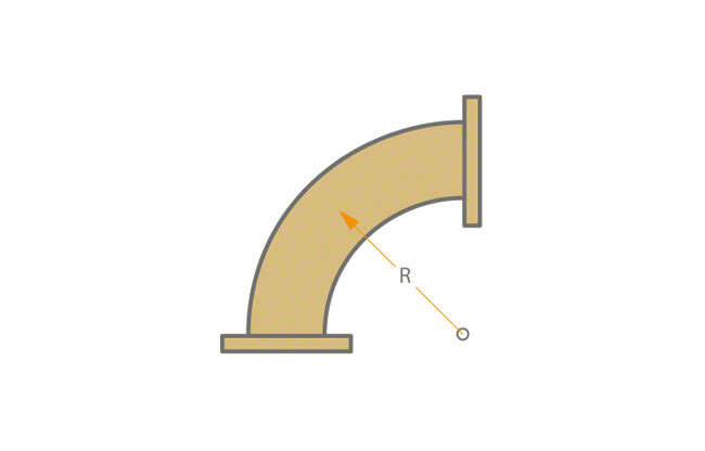
Fig. 1 Fitting: 90° pipe bend
Y-branch
- Y-branches' fluid dynamic characteristics make them preferable to tees.
See Fig. 2 Fitting

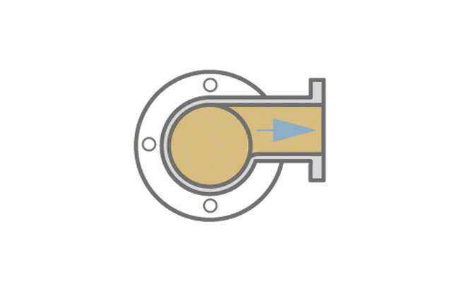
Fig. 2 Fitting: Y-branch
Diffusor
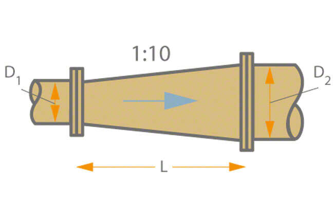
- Its face-to-face length (L) should be approximately L = 5 ∙ (D2 – D1)
(D = pipe diameter) when used as a diffuser in flow direction. Diffuser outlets (e.g. in the case of low-lift pumping stations and pumps for use in low-lift pumping stations should be sized such that the discharge velocity (v) (see Flow velocity) is 1.0 to 1.5 m/s.
See Fig. 3 Fitting
Nozzle-shaped reducer
- In contrast to a diffuser, the face-to-face length of a fitting used as a reducer can be much shorter. A nozzle-shaped reducer features favourable flow characteristics.
See Fig. 4 Fitting
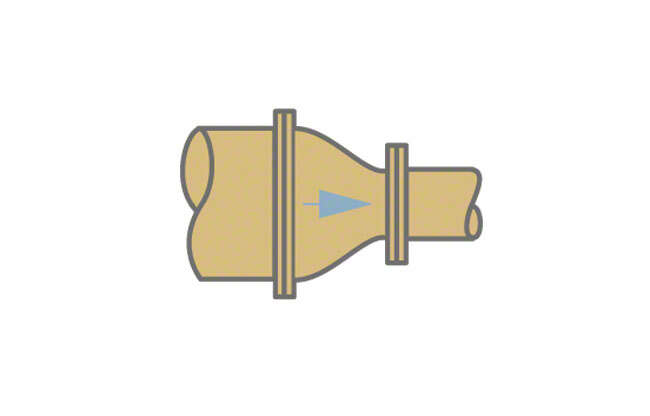
Fig. 4 Fitting: Nozzle-shaped reducer
Reducer for avoiding air pockets
- Eccentric reducers should be installed in horizontal suction lines to avoid the formation of air pockets (see Formation of air pockets).
See Fig. 5 Fitting
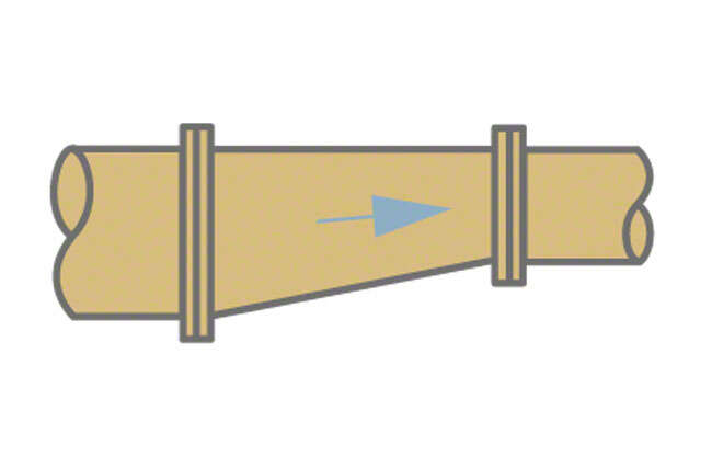
Fig. 5 Fitting: Reducer for avoiding air pockets
Branch fitting for avoiding air pockets
- Eccentric branch fittings should be installed in horizontal suction lines to avoid the formation of air pockets.
See Fig. 6 Fitting - For further fittings see bellmouth, intake chamber and intake elbow (see Inlet conditions).
