T

Tank farm pump

Tank farm pumps are submersible pumps which are used in tank farms for transporting liquid raw, intermediate and finished products in chemical and petrochemical plants as well as in refineries. Plant operators select the type of pump depending on the required operating data and on whether the fluid to be pumped is highly volatile, flammable or toxic.

Types of pump

In many cases, a specific type of pump is required to comply with the applicable national regulations. According to the regulations of some countries, for example, pumps for tanks containing flammable or toxic fluids must be either submersible pumps with a sealed passage of the pump shaft (see Shaft seal) out of the tank, self-priming pumps arranged on the tank, or submersible motor pumps.

For pumping highly volatile and flammable liquids ductile materials such as steel and nodular cast iron (see Material selection) are recommended for safety reasons and to prevent corrosion. With the exception of submersible pumps with a separate discharge line (see Pump system), whose shaft seal is not in contact with the fluid handled, pumps with conventional drives are generally fitted with mechanical seals. Submersible pumps are usually designed so they can be inserted into standardised manholes with the footplate of the pump covering the manhole.

The use of submersible pumps becomes problematic when the tank height requires large installation depths. This makes the maintenance of such pumps rather difficult as transportable lifting equipment is required for pulling out the pump. It can also lead to problems in the case of several product-lubricated intermediate bearings (see Plain bearing), low fluid levels and intermittent operation if the fluid pumped is very aggressive or tends to crystallise (e.g. sodium hydroxide and potassium hydroxide).

For pumping melts or highly viscous fluids (see Viscosity) tank farm pumps are often fitted with a heating jacket to keep the fluid within the pump in a pumpable condition. Liquefied gas tank farms require a special pump design (see Liquefied gas pump).

Tank flow

A certain level of flow volume/velocity is required in the activated sludge tanks of waste water treatment plants; the flow prevents sediments from settling on the tank's floor and ensures bacteria and micro-organisms are provided with oxygen needed for the degradation of waste water pollutants. Submersible mixers are used to generate flow in the tanks.

Telemetry

Telemetry describes the transmission of measured values recorded by a measuring element such as a sensors to a distant point of reception.

Teleservice

Teleservice describes the exchange of data and information between technical installations that are located some distance apart. The aim is to monitor the conditions, identify errors and faults, perform diagnostics, carry out maintenance and perform data analysis with a view to optimise the installation.

Data is transferred by means of remote data transmission (see also communications system).

Temperature

Temperature is a physical and thermodynamic property which describes the thermal energy of a material. Its SI unit is the Kelvin (K). In the DACH countries (Germany, Austria, Switzerland), the degrees Celsius scale (°C) is also permitted, and the degrees Fahrenheit scale (°F) is used in the USA (see also Metrology).

Temperature measurement

The temperature in centrifugal pumps is usually quantified using a contact thermometer, whose temperature sensor physically contacts the fluid to be measured. The pronounced exchange of heat between the fluid and the temperature sensor is enabled e.g. via the arrangement in the volume
flow, the material(s) selected, and the design of the temperature sensor. Heat should not be transported to the outside by the temperature sensor, however.

The temperature measuring method used is determined by the respective temperature range and special requirements such as the installation conditions, accuracy, dynamics of the measurands, and signal transfer of a specific measuring task. See Fig. 1 Temperature measurement

This is an embedded image

Conventional contact thermometers are fluid thermometers, resistance thermometers, and thermocouples. Relevant, valid guidelines are e.g. VDE/VDI 3511, DIN 43735 and DIN 16160.

Temperature rise in electric motors

The power loss in an electric machine (see Drive) leads to the build-up of heat in active parts such as the winding and core packs (also see Motor protection). Increases in the winding temperature not only reduce the lifetime of the insulation, but can also cause the electric machine to fail without warning if heat reaches dangerous levels.

Impermissible temperature rises can be the result of improper cooling or an overload, which increases the current requirement of electric motors.

The insulating material used determines to what extent heat may build up in the motor. IEC 60034-1 covers the thermal resistance of insulating materials, thermal classes, and methods for determining overtemperature.

Temperature sensor

A temperature sensor is an electronic component. The process of converting temperature into an electrical variable is frequently based on the principle of temperature-induced changes in resistance (e.g. PT 100) or the thermoelectric effect (e.g. thermocouple) (also see sensor and thermoelectric
series).

Terminal

Terminals in electrical engineering applications allow wires, cores, and leads to be detachably connected. To prevent the flow of current from being interrupted, they are mechanically fixed to a conductive body via a screw or spring.

A special type of terminal is used to manually disconnect circuits: the isolating terminal.

Terminal gland

The terminal gland facilitates the supply of current through the motor housing to the winding. Submersible windings use a pressure-sealed terminal gland in the form of a copper connection bolt as is used fo wet rotor motors, e.g. in glandless pumps for. The bolt is insulated at the housing wall by insulating sleeves, sealed by an O-ring, and pressure-sealed by a threaded bushing. See Fig. 1 Terminal gland

This is an embedded image


Terminal identification

A terminal identification is a marking that facilitates connecting leads or troubleshooting via a circuit diagram. Terminal markings include letters or numbers and are found directly on the terminal or lead to be connected.

Thermistor

The thermistor is a heat-sensitive electrical resistor that reliably alters its resistance value when a change in temperature is encountered. The NTC resistor has the opposite characteristic of the PTC resistor.

Thermocouple

A thermocouple is a measuring instrument (also see Sensor) whose measuring principle is based on the thermoelectric effect. It comprises two different metals that are joined at one end and is used to measure temperature.

Thermoelectric series

Heating a soldered or welded connection joining two metals (e. g. to measure temperature) with cold, free ends leads to a thermoelectric voltage. This voltage represents the difference between the subsequently listed values, which refer to platinum as the reference point (zero) and to 100 °C as the difference in temperature. See Fig. 1 Thermoelectric series

This is an embedded image


Three-phase current

Three-phase current can also be called three-phase alternating current or three-phase electric power and is used in the low-voltage network for end consumers (public power grid). The current carried here is limited to 400 volts in Germany and elsewhere.

When three coils in a generator are arranged uniformly in circle, three corresponding (i.e. offset) alternating voltages are produced that reach their maximum amplitudes consecutively, at different times. These offset voltages are described by the phase angle.

With three-phase alternating current, phases are offset by 120 degrees. See Fig. 1 Three-phase current

This is an embedded image

The formula for calculating a single alternating voltage in a system carrying three-phase alternating current is:

This is an embedded image

Power companies try to load the three phase conductors as uniformly as possible. When the three-phase alternating current system is branched into separate AC lines as found in households, symmetrical loading is no longer ensured. A neutral conductor (four-conductor system) is therefore added to carry the compensating currents as dictated by the degree of asymmetry between the external conductors. This neutral conductor, like the external conductors, is an "active conductor" of the three-phase system that can carry current in normal operation, as opposed to an additional earth conductor. See Fig. 2 Three-phase current

This is an embedded image

Three-phase current can be used in a delta or star configuration.

Star configuration

When a star configuration (three-phase system) is used, the three phase conductors in a three-phase system are interconnected at one end. The resulting convergence forms the centre point, or star point, which is connected to the neutral conductor (N). The free ends are then connected to the external conductors (L1, L2, and L3). See Fig. 3 Three-phase current

This is an embedded image

This arrangement is beneficial in that two different voltages can be tapped for a symmetrical load (i.e. the u, v, and w phases have the same impedance). Based on typical phase voltage in Germany, 230 V are carried between the external conductor (L1, L2, or L3) and the neutral conductor (N) . If the voltage between the two external conductors is tapped (e.g. L1 and L2), 400 V are obtained.


Combined use of the three phase conductors takes place in electric motors (three-phase motor) for example. When the voltages in a motor are routed by three coils arranged in circle, a rotating magnetic field is again produced and triggers rotation of a basic squirrel-cage rotor.

The ends of the three phase conductors are labelled as follows:

This is an embedded image

To operate an electric motor in a star configuration, external conductors L1, L2, and L3 are connected to conductor ends u1, v1, and w1:

This is an embedded image

The remaining ends of the phase conductors (u2, v2, and w2) are jumpered (interconnected) to realise the aforementioned star point.

Delta configuration

In a delta configuration (three-phase system), the three phase conductors of a three-phase system are connected in series, whereby the end of one phase conductor is connected to the opposite end of the next conductor. This gives rise to three intersecting points (u1, v1, and w1), to which the external conductors are connected and their designations are standardised: L1, L2, and L3 (before: R, S, and T). 

See Fig. 2 Alternating current

A neutral conductor (N) is not required as for the star configuration. In consumer power networks in Germany and Central Europe, 400 volts are carried at the intersecting ends of the phase conductors, while the individual external conductors "earth" 230 volts. See Fig. 4 Three-phase current

This is an embedded image

The delta configuration (three-conductor system) is normally used in industrial applications involving powerful machines and to carry electrical energy across large distances.

Throw

In fire-fighting it is common practice to test a fire-fighting pump's function by checking the water jet's height or throw from the jet pipe's nozzle. In order to achieve a sufficient fire-fighting effect, the pressure (i.e. the pressure above atmospheric pressure) in the jet pipe should be min. 4 bar.
See Fig. 1: Throw

Thyristor

The thyristor is a semiconductor switching element that comprises at least four semiconductor layers, each of which has a different doping profile.

They are used to electrically adjust the rotational speed of three-phase motors and as power converters in frequency inverters.

Tightness

Tightness is a property of material structures and is a relative concept that always refers to specified conditions. It is verified by means of a leak test (also see valve).

Time

Time (t) is a physical dimension. It extends from the past, through the present and into the future. The SI unit for time is the second (s).

Torque flow pump

The torque flow pump is also referred to as vortex flow pump Its hydraulic power (see pump power output) is transmitted to the fluid handled by a rotating disc provided with ribs (free-flow impeller).

See Fig. 3 Sewage pump See Fig. 3 Waste water pump

This free-flow impeller is particularly suitable for use in pulp pumps and waste water pumps. As the impeller only acts indirectly on the fluid handled, the risk of clogging and sensitivity to gas in the fluid are reduced.

Torsion dynamometer

Torsion dynamometers are machine components that are usually installed between the motor and driven machine or between the generator and prime mover. They transfer power while measuring torque. Torsion dynamometers measure torque by measuring the torsion angle of a specific
shaft piece, or torsion bar (see Power measurement)).

Total head

The total head HBN, calculated from a datum level BN, is the mechanical energy of the fluid handled, per unit weight. The unit of total head is metres (m).

This is an embedded image

z     Geodetic height of given point above BN
pb   Atmospheric pressure
p     Overpressure (positive) or underpressure (negative) in relation to pb
ρ     Density of fluid handled
g     Gravitational acceleration
v      Flow velocity

A graphic representation of the total head at various points within a pump system can be found in EN 12723, for example. See Fig. 1 Specific energy

Total pressure

The total pressure ptot is the sum of all pressures present in a reference system. According to Bernoulli (see Fluid mechanics), this pressure comprises the static pressure p, the dynamic pressure pdyn and the geodetic component (ρ ∙ g ∙ z) being present in a fluid along a stream line in a frictionless flow.

Total tolerance

The total tolerance is the combined manufacturing tolerance and measurement uncertainty for measurements that are taken to provide proof of a guarantee.
The acceptance test codes in DIN EN ISO 9906 contain tolerance factors that make it easier to apply the combined manufacturing tolerance and measurement uncertainty that always have to be taken into account during the acceptance test for the individual operating parameters. These tolerance factors for the flow rate (± tQ), pump head (± tH) and pump efficiency (± tη) must be applied to the guaranteed point. See Fig. 1 Total tolerance

Variable

Symbol

Class 1 %

Class 2 %

Volume flow rate

tQ

± 4,5

± 8

Pump discharge head

tH

± 3

± 5

Pump efficiency

    η

    -3

    -5

The head and flow rate guarantee is fulfilled if the H/Q curve determined from the measurements intersects or at least touches the vertical and horizontal bar of the tolerance cross. See Fig. 2 Total tolerance

This is an embedded image

The efficiency is derived from the point where the measured H/Q curve intersects the straight line running through the agreed operating point QG, HG and the zero point of the H/Q axis as well as from the point where a vertical is intersected by the η(Q) curve calculated from the measurements. The guarantee condition for efficiency is deemed to be within the tolerance limits if the value of this quantity is greater than or at least equal to the value for ηG ∙ (1 − tη) at this intersection point.
In the new version of DIN EN ISO 9906, the classes for assessing a pump measurement and the measurement results have been extended from 2 to 5. This also results in changes to the relevant total tolerance. See Fig. 3 Total tolerance

This is an embedded image

In accordance with this extended classification system, diagrams are available to illustrate the conditions for fulfilling the guarantee. See Fig. 4 Total tolerance

This is an embedded image


TPM

TPM is the abbreviation for Total Pump Management, which is a modular service concept for pumps, valves and associated systems that applies regardless of the manufacturer. The three features of Services, Reliability and Conditions cover all the modules that can be combined to create a service contract. See Fig. 1 TPM

This is an embedded image


Transient

If a parameter is not able to maintain a constant value over time, but changes relative to time, it is classified as transient or non-steady-state (see also Transient flow).

Transient flow

The flow of a fluid is transient or unsteady if its flow parameters (i.e. velocity and pressure) are dependent not only on the position in the coordinate system used to describe the field of flow, but also on time. A distinction is made between three different types of transient flow phenomena.

Transient flow phenomena

As a result of velocity changes at a fixed point in space, local accelerations or decelerations create additional mass forces in a transient flow which cause corresponding changes in pressure. These can manifest themselves as marked short-term pressure increases resulting from the sudden closing of a shut-off element in a long, fluid-filled pipe or as increased pressure losses caused by pulsating flow.

Periodically transient flow phenomena can, given a sufficiently low frequency of changes, often be treated as quasi-steady phenomena. On an averaged basis, they are at any given point in time subject to the same flow conditions as steady flow

The flow through a rotating set of vanes (see Impeller) is, strictly speaking, always a transient flow if viewed from a stationary coordinate system (see Absolute velocity).  At fixed point in space, both velocity and pressure change periodically as the vanes pass.

However, the flow in an impeller and its immediate vicinity can be considered  steady as long as it is described using a system of coordinates which rotates with the impeller (see Relative velocity). The centrifugal and Coriolis forces arising in this relative system must be taken into account.

Transverse thruster

A transverse thruster is used as a manoeuvring aid on board ship at slow speeds, for example to enable the vessel to be independent of tugs. They are particularly useful for turning manoeuvres in narrow harbour basins, when travelling through canals, and when docking and casting off. See Fig. 1 Transverse thruster

This is an embedded image

Transverse thrusters are propeller pumps, which are also called bow thrusters because they are installed in the bow.

Large vessels often have two transverse thrusters arranged one behind the other, because a single transverse thruster of the same performance would have too large a diameter. Some special ships may also be equipped with an additional stern thruster.

For manoeuvring, the propeller pumps a flow of water through the transverse tunnel either to port or starboard. This generates a reaction force which displaces the ship in the opposite direction to the flow of water.

The change of direction of the flow of water can be effected either by changing the direction of rotation of the propeller with the aid of reversing the direction of rotation of the motor or, while maintaining the direction of rotation, by using a variable pitch propeller (see Impeller blade pitch control).

Travelling screen

A travelling screen is a continuously moving, belt-like fine-mesh screen that is mainly used to clean cooling water in thermal power stations; it is positioned between the coarse screen and the intake chamber of cooling water pumps. 

The dirt that becomes lodged in the screen can be removed through spraying.

Tribology

Tribology is the study of friction. Bodies interact with the environment and with other bodies via their surface and therefore their volume. Interfaces are formed between the points of contact. To assess friction and wear behaviour, it is essential to have a knowledge of the surface and interface characteristics. Topography and roughness parameters are characteristic tribological properties.

Tubular casing pump

A tubular casing pump is a centrifugal pump, in which the fluid handled, having passed the impeller and the diffuser, flows through the tube shaped pump casing (in the case of vertical tubular casing pumps, the column pipe is concentric with the pump shaft. The most common tubular casing pumps are vertical pumps.

In the case of a wet well installation, the pump's bellmouth is submerged in an intake chamber which is either open at the top or covered; dry-installed tubular casing pumps are bolted onto an intake elbow at their suction end, or are connected in a leak-tight manner to the cover of an intake chamber.

In all cases, it is important that the inlet conditions of tubular casing pumps are carefully studied. The tubular casing and discharge elbow can be made of concrete for reasons of economy. See Fig. 7 Cooling water pump

The impeller is either an axial impeller or mixed flow impeller depending on the specific speed. The diffuser leads into the column pipe and, depending on the installation depth, several lengths of column pipes can be bolted together in succession. As a result, the pump shaft needs to be longer and it must be supported by several bearings. The discharge elbow at the end of the column pipe guides the flow towards the end of the pump discharge nozzle.

The shaft exits the tubular casing at the level of the discharge elbow and is sealed by a gland packing or a mechanical seal. The motor stool arranged above accommodates the thrust bearing (plain bearing, rolling element bearing) and provides access to the shaft coupling between pump and drive or gear unit (e. g. spur gear).

The drive for pump control is also accommodated in the motor stool. The impeller blade pitch adjustment of the propeller pumps  is predominantly actuated through the hollow drive shaft. Pre-swirl control of mixed flow pumps is usually actuated from here via special universal joint shafts.

The shaft guide bearings are maintenance-free, water-lubricated ceramic plain bearings. These bearings do not require clean fresh water or a filtered portion of the fluid handled for lubrication, and they can cope with handling heavily contaminated, unfiltered fluids.

As the installation and removal of the tubular casing is rather cumbersome due to the weight and bulky proportions of the items involved, tubular casing pumps in pull-out design allow the complete withdrawal of the hydraulic components such as impeller and diffuser including shaft and bearings (rotating assembly)  from the tubular casing (see Pump in pull-out design).
See Fig. 1 Tubular casing pump

This is an embedded image

For this purpose, the discharge elbow must be designed with an opening at the drive end whose diameter is equal to the tubular casing and which is sealed by a discharge cover. In this case an inspection or replacement of the rotating assembly only requires that the motor and motor stool are dismantled and that, after the discharge cover bolts have been undone, the complete rotating assembly is withdrawn. The discharge-side connection and the suction-side connection (if applicable) of the tubular casing remain undisturbed.

If several identical pumps are installed, a complete spare rotor (rotating assembly) can be kept on stock for replacement.

Especially when large nominal diameters are required, tubular casing pumps in pull-out design are the preferred choice. Their installation options are varied and are usually governed by the site conditions and characterised by the installation types the pump manufacturer can offer.

The pump impeller is continuously immersed in the fluid handled in order to eliminate the need for special suction devices or booster pumps. In the case of dry installation, the suction side of the pump must be connected to the intake elbow or to the cover of the intake chamber so as to be water- and air-tight.

All this amounts to additional capital investment costs which are, however, compensated by the advantages that the pump casing can be very short and that the pump is accessible for inspection from the outside at all times.

A tubular casing pump for wet well installation is submerged in the fluid handled at its inlet end. Thanks to its straightforward installation, a wet-well installed pump is employed much more often than a dry-installed tubular casing pump.

Another aspect to be determined for installation is the question of whether the tubular casing pump's discharge nozzle should be situated above or below floor level (the latter being the case with irrigation pumps). This decision should be made at the site.

Finally it must be decided how the weight of the drive is to be supported. The motor stool can be placed directly on the discharge elbow situated above floor level (provided the pump set does not become too "top-heavy" as a result), or the motor stool can be placed (cantilevered) over the discharge elbow without exerting any load on it (cantilevered motor stool), or the motor stool can be installed on a floor of its own at the engine room's next level up.

The rotating shafts and couplings must be equipped with appropriate contact guards. In certain rare cases – small nominal diameters and short overall lengths – the complete pump set can be installed on the intake chamber's floor by means of a special pump foot

Tubular casing pumps are primarily used as cooling water pumps, but they are also employed as pumps for low-lift pumping stations as well as booster pumps in seawater desalination systems.


Tuft

Tufts are used to make flows visually apparent. This is achieved by attaching a woollen thread to one end of a probe and holding the thread in the flow. The loose end moves with the flow and provides initial indication of the direction of flow in a particular area.

Turbine mode

A standardised centrifugal pump can be run in reverse and used as a turbine without having to make any changes to the design of the casing or the impeller geometry. Selection only requires a few rules with regard to volume flow rate (Q), head (H) and rotational speed (n) to be observed.

It is in most cases possible to achieve the same high level of efficiency with pumps run in reverse as in conventional operation. The efficiency of a doubleentry volute casing pump is approx. 85 %. %. This does, in fact, imply the existence of a best efficiency point  in turbine mode which allows an almost shock loss-free fluid flow inside the machine. At this operating point the pump used as turbine (PaT) runs as smoothly as a pump that is used in conventional mode operating at its design point The outgoing flow is almost vortex-free, andpipe vibrationsnoise or wear are very low.

In optimum turbine mode, the reverse running pump's influence on the flow pressure curve is that of a throttle. In contrast to common shock loss throttles, the PaT however transmits the largest portion of the energy withdrawn from the fluid flow to the outside via the shaft.

The energy thus extracted can then either be re-introduced to the fluid handled at another point in the system or re-used as energy (in a mechanical or electrical form) in many other ways, e.g. if used in seawater desalination systems (see Energy recovery). 

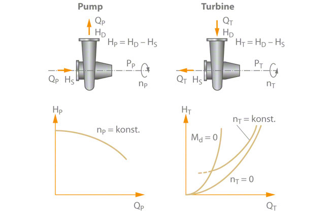
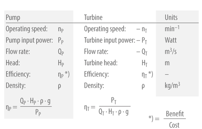
The difference between turbine and pump mode is the change in the direction of rotation which is designated with a minus sign. In addition, the flow rate and turbine head are always greater in turbine mode at BEP (best efficiency point) than the flow rate and head are in pump mode at the same rotational speed. In general, turbine efficiency corresponds to pump efficiency.

It is also possible to convert the head, flow rate and output power relative to the rotational speed in accordance with the normal affinity laws due to similar velocity triangles in pump and turbine mode. See Fig. 1 Turbine mode

This is an embedded image

The integration of a PaT (pump used as turbine) into a pressure control system is ideally performed via a bypass. line. As the centrifugal pump is not fitted with adjustable or variable pitch diffuser vanes external control devices (control valve I and II) are required in turbine mode. A shutoff valve should be installed upstream of the pump to enable its shutdown for maintenance work.

See Fig. 2 Turbine mode

This is an embedded image

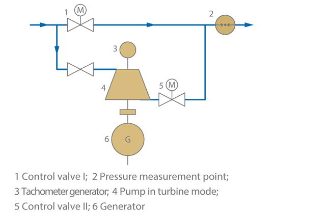
Feeding the recovered energy into the electrical grid via an asynchronous motor used as a generator is both an economical and technically straightforward procedure, with the unit's speed (apart from a load-dependent minor slip) being kept constant. An even simpler way of utilising the recovered energy is to aid or replace an installed electric motor by directly connecting the PaT to a machine.

Generating electricity for isolated operation requirements is possible. However, elaborate control is required to maintain a constant frequency in the event of fluctuating system loads. See Fig. 3 Turbine mode

This is an embedded image

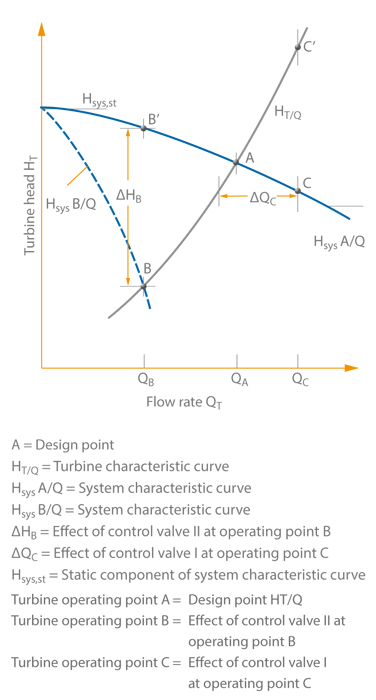
Similar to the pump's operating point, the turbine's operating point is given by the intersection between the turbine characteristic curve HT(Q) and the system characteristic curve Hsys(Q). If the volume flow demand decreases, the constant speed PaT (pump used as turbine) is no longer able to exploit the pressure potential available (point B). As a consequence, the excess energy Δ HB must be reduced via control valve II to ensure that a constant pressure is maintained on the outlet side.

If the volume flow requirement rises to point C, the increased volume flow rate QC is obtained by opening control valve I. The PaT alone would reduce the pressure too much (point C') which would lead to a drop in pressure on the outlet side.

The pressure downstream of the control system serves as controlled variable for throttling valves I and II.

The use of a constant speed machine results in the above-mentioned problems: The PaT is only designed for a defined volume flow rate and a defined pressure gradient. All other operating conditions must be controlled by the throttling elements.

The energy potential is not fully exploited. The PaT and its control equipment are, however, straightforward technical components which are favourably priced and easy to operate. In many instances a reverse running standard asynchronous motor is suitable for use as a generator.

When using a variable speed generator instead of an asynchronous motor, it is possible to vary the volume flow rate (QT) at a constant turbine head (HT) without additional throttling devices.

The pump to be used as turbine is selected to ensure that its flow rate coincides with the most frequently required volume flow. If the system's operating mode changes, i.e. if a lower flow rate is required, the rotational speed is increased; if, however, the volume flow demand increases, the speed is reduced.

This fact has a negative effect on the overall efficiency of the system. While efficiency drops very sharply with increasing speed, constant pressure reduction and thus a decreasing volume flow rate, the PaT's operating limit is very quickly reached with increasing volume flow rate and thus a decreasing speed (approx. 1.5 times the volume flow rate at BEP (QT.BEP)).

The energy account of a pump/turbine combination is balanced, which means that the turbine output power is equal to the pump output power.

The pump/turbine set thus serves as an energy converter, and there is no need to connect it to an electric motor.

Compared with conventional turbines, pumps used as turbines offer a range of both benefits and drawbacks. 

See Fig. 4 Turbine mode

AdvantagesDisadvantages

Broad performance range offered by a closely spaced selection chart of standard pumps

Due to the lack of control equipment, possibilities for matching the system to actual demand are very low
Wide range of selection options with regard to materials, sealing elements and other accessories


Favourably priced standard productsSlightly inferior efficiencies compared with turbines designed and manufactured to order for particular specifications
Short delivery times
Use of ring-section pumps if high turbine heads and low flow rates are required
Minimum control and monitoringNo adjustable diffuser elements

Fig. 4 Centrifugal pumps in turbine mode

Centrifugal pumps and turbines are turbomachines which either transfer energy from a rotor to a fluid or from a fluid to a rotor. This relationship is expressed by the Euler equation.

See Fig. 5 Turbine mode

This is an embedded image

Important characteristic curves for turbine mode
See Fig. 6 Turbine mode

  • Resistance curve a: No-load curve at torque (T) = 0
  • Resistance curve b: Operating curve at constant speed (n)
  • Resistance curve c: Resistance curve at locked rotor, speed (n) = 0

This is an embedded image

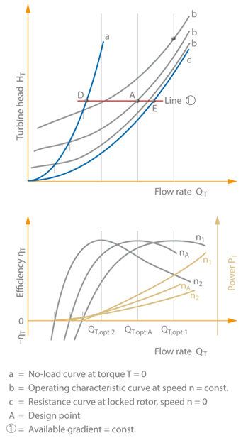
So far, only the operating curve (b) has been considered for the selection of the pump used in turbine mode. The resistance curves (a, c) with torque (T) or rotational speed (n) equalling zero are only relevant in the event of malfunctions. If the power output at the shaft is not used, for instance, due to an electric mains failure, the PaT (pump used as turbine will adopt the operating point which is the intersection of the system characteristic curve and the no-load curve.

If the system characteristic curve is assumed to have a constant gradient, then point D can be determined on line 1. The speed at this point (see Runaway speed) is considerably higher than the operating (nA) and is reached within a very short time following the sudden removal of the load on the generator.

In order to prevent damage to the PaT/generator set as a result of these operating conditions, both machines must be designed to withstand the resulting circumferential speeds. The rotational speed change is accompanied by an equally abrupt reduction in the volume flow rate which results in considerable pressure surges in the piping and in an additional, short-term increase in speed.

The resistance curve (c) shows the H / QT curve at locked rotor.

In the region of the design point A, the operating curves b of radial impellers are located close to the resistance curve c and, in the overload region, they run almost parallel to it at a relatively small distance. This physical characteristic can be utilised to reduce the risk of surge pressure. For this purpose the PaT is fitted with a quick-locking brake which becomes immediately operative upon generator load rejection to prevent the turbine set from reaching the runaway speed. The turbine set is decelerated to zero speed. The new operating point on the resistance curve c is located at point E. See Fig. 6 Turbine mode

The resultant change in volume flow rate (ΔQ) is, however, significantly lower than that which would result from operation at zero torque. Fig. 6 also shows the development of efficiency ηT and power PT as a function of flow rate QT.

Turbomachinery

Turbomachinery includes all types of machines through which a fluid or a solids-laden fluid flows and which are equipped with a vaned impeller for the exchange of mechanical energy and flow energy.

In contrast to positive displacement machines (see Positive displacement pump) flow deflection by the impeller vanes is the characteristic feature of turbomachinery in this energy exchange (see Principle of conservation of momentum). 

Depending on the direction of the energy transfer, i.e. from the turbomachinery’s shaft to the fluid or vice versa, a distinction is made between "driven machinery" (e. g. centrifugal pump, turbo-compressor, ventilator, aircraft propeller or airscrew, ship's propeller) and "prime movers" (e. g. steam, gas, wind, liquid, and in particular, water turbines).

Turbulent flow

In contrast to laminar flow, turbulent flow is characterised by an additional, macroscopic (visible) momentum exchange of individual flow layers. These turbulent fluctuations are irregular and time-dependent phenomena.

Twin pump

A twin pump is a circulating pump consisting of two separate centrifugal pumps in a common pump casing and a spring-loaded change-over flap located in the discharge nozzle. A twin pump can be used for parallel operation (additional pump start-up in case of peak load) as well as for single-pump operation (one pump on stand-by). For this reason it is particularly suitable for hot water heating systems (e. g. circulator pump) in which a stand-by pump which can be started up at any time is required to comply with safety regulations or to provide a higher level of comfort.

In this case one centrifugal pump serves as the duty pump and the other as the stand-by pump.

Electrical switchgear ensures that the stand-by pump is started up immediately in the event of a duty pump failure. The necessary shut-off elements (see Valve)  for the change-over are integrated in the pump set.

A twin pump only has one pump suction nozzle and one discharge nozzle.  Continuously variable differential pressure control adjusts the flow rate in low-flow operation. See Fig. 3 Circulator pump


Two-phase flow

Two-phase flow is a flow in which two different aggregate states of a substance or of two different substances are simultaneously present. The possible combinations include gaseous/liquid (see Gas content of fluid handled), gaseous/solid and liquid/solid (see Solids transport). 

Examples of two-phase flow are transport processes where one medium is transported in another (e. g. hydraulic or pneumatic transport), or the frequently undesirable entrainment of gas or vapour bubbles (see Cavitation) which have come out of solution in fluid flows.

In two-phase flow, further factors are involved in addition to flow parameters such as the Reynolds number. The concentration, which can be expressed in the form of volume ratio or mass ratio of the two phases, represents an important factor.

Various flow or phase distribution patterns can occur in a two-phase flow. These are influenced by the concentration ratio of the phases, the slip ratio (difference between the flow velocities of the two phases) and the orientation of the piping (horizontal, vertical). Flow patterns of gaseous/liquid two-phase flow include bubble flow, plug flow and film flow.

Various, primarily empirical, calculation methods are applied to establish the head loss in a two-phase flow in straight pipes. Some of them take the influence of the flow pattern and the orientation of the piping (horizontal, vertical) into account.

In the case of gaseous/liquid two-phase flow, a distinction must be made between flows whose gaseous phase represents the vapour state of the liquid also present (e. g. water/steam) or flows in which the gaseous phase is a different substance (e. g. water/air). In the first of these two cases, phase change phenomena such as vaporisation and condensation may play an important role.

Different densities  of the two phases mean that phase separation in the form of the settling of solid substances or the rising of bubbles may occur in two-phase flows at low flow velocities under the influence of gravity. This kind of separation will be even more pronounced under the influence of centrifugal forces (e. g. in elbows, impellers) and at higher flow velocities, with the constituents of lower density being subjected to the action of forces which drive them towards the centre of the bend or centre of rotation.

This effect can result in the cut-off or stalling of the flow (see Operating behaviour) in a centrifugal pump handling a gaseous/liquid two-phase flow. In the case of liquid/solid two-phase flow containing abrasive solid particles (see Abrasion), the possibility of wear on components exposed to the flow must be taken into account. This is particularly likely to take place in the region of curved stream lines (see Solids transport, Pulp pumping). 

The lift effect based on buoyancy of a two-phase fluid involving a mixture of water and air is exploited in vertical underwater piping through the use of air lift pumps, while three-phase flow is utilised for hydrotransport (e. g. air lift) (see Type of pump).

Type of protection

The types of protection for electrical operating equipment (e. g. electric motor) are specified in DIN 40050, 1980. They encompass protection against accidental contact, foreign bodies, and water. The internationally agreed types of protection start with the code IP ("International Protection), which is followed by two digits. The first digit specifies the protection provided by the enclosure with respect to physical contact or foreign bodies, and the second number specifies the protection against moisture. See Fig.1 Type of protection

This is an embedded image

Special types of protection are designated by the letters W (weather protection) and R (pipe connection for motor cooling).

Type of pump

The pump's designation does not always provide information on the pump type, as very different criteria are used to designate a pump.

Criteria for pump classification

  • Operating principle or function
  • Design characteristics (impeller type, impeller arrangement, casing type, installation type)
  • Purpose or application (with regard to the pumps' operating mode, use in a pump system, fluid handled)
  • Drive
  • Pump material

Operating principle or function

Centrifugal pump 

  • This type of hydraulic turbomachinery is characterised by the transmission of energy by impeller vanes or blades as they deflect the flow of a fluid (see Fluid mechanics). In contrast, positive displacement pumps are characterised by the displacement of fluid volume.
  • The head of a centrifugal pump is proportional to the square of the pump speed (see Affinity laws). 

Positive displacement pump

  • The operating principle of a positive displacement as utilised by positive displacement pumps is characterised by the periodic change in volume.
  • In addition, the expansion action of vapours or gases can be used for displacement purposes (pulsometer, Humphrey pump).

Jet pump (eductor-jet pump)

  • The pressure differential in a nozzle created when a motive fluid is directed through it is used to convey a second fluid. The motive fluids can be liquids, gases or vapours.
  • As these pumps have no moving parts, their design is extremely simple.
  • Their powers and efficiency are limited.

Air lift pumps (mammoth pumps) 

  • Air lift or mammoth pumps' mode of operation is based on the lift action of a mixture of liquid and gas (see Two-phase flow)
    Therefore, they can only be used in pumping stations with sufficient geodetic height differences.

Hydraulic ram 

  • Hydraulic rams use the kinetic energy of a flowing liquid column by converting it into another form of energy (e. g. pressure energy) via a sudden deceleration action.

Elevators

  • Elevators lift liquids to a higher level without changing their pressure by using bucket wheels, bucket elevators, Archimedean screws (see Archimedean screw pump) and similar devices.

Electromagnetic pump

  • Electromagnetic pumps' mode of operation depends on the direct action of a magnetic field on the ferromagnetic fluid handled; their application is therefore limited to the pumping of liquid metals.

Design features

As each operating principle requires its own fundamentally distinct pump design, categorising pumps according to their design features is only relevant when distinguishing between different pumps which share a common operating principle.

The design differences described below refer to centrifugal pumps.

Impeller type 

  • Depending on a centrifugal pump's specific speed its impeller may be a radial, mixed flow or axial impeller
  • Radial and mixed flow impellers can be designed with open (without shroud) or with closed channels (with shroud).
  • Axial impellers (propellers) can be cast in one piece with their hubs. The blades (see Vane) can be attached to the hub so as to allow blade pitch adjustment or variable pitch control in order to improve the characteristic curve or enable control during operation (see Impeller blade pitch adjustment). 
  • The arrangement of the propeller blades does not necessarily have to be perpendicular to the pump shaft (see Propeller pump), especially if the propeller is intended for high heads (while maintaining its design advantages with regard to control) and has to cope with radial (i.e. diagonal) flow velocity as a result. 
  • In addition, specialised impellers are available for special fluids including the  single-vane, two-channel, three-channel or free-flow impeller (see Torque flow pump) and peripheral impeller (see Peripheral pump). 

Impeller arrangement 

  • The impeller of a centrifugal pump can be supported by bearings on both sides or on one side only (overhung).
    Using an overhung arrangement eliminates the need for a second shaft seal, but increases shaft deflection, all else being equal.
  • In the case of high flow rates a between-bearings impeller can be designed as a double-entry impeller (see Double-suction pump) which also helps to balance the axial thrust
  • High heads can be achieved by a multistage impeller arrangement (see Multistage pump). If axial thrust balancing is required in a multistage arrangement, half of the impellers can be mounted in back-to-back arrangement provided that there is an even number of stages
  • Combinations of double-entry and multistage arrangements are also feasible.

Casing type

  • Most of the distinctive pump design features relate to the wide variety of possible casing types (see Pump casing). 

Installation type

  • The various modes of installation involve a whole range of different design features.
  • First of all, a distinction is made between centrifugal pumps with horizontal (see Horizontal pumps) and vertical (see Vertical pump) shaft.
  • Centrifugal pumps can be installed dry (see Dry installation) or wet (see Wet well installation). Wet-installed centrifugal pumps are also referred to as submersible pumps  and are submerged in the fluid handled as are most tubular casing pumps. 
  • In the past, centrifugal pumps with inclined shafts were sometimes used in low-lift pumping stations. 
  • A further distinguishing feature is the centrifugal pump's attachment to the foundation. The pump may stand on its own feet (in the case of horizontal pumps with "feet at the bottom of the casing" or "with feet arranged at shaft centreline") or may be flanged to the drive (in the case of close-coupled pumps.
  • There are further differences in the way the pump casing is connected to the drive housing (e.g. flanged motors or motor stools/drive lanterns).
  • Different baseplate, arrangements are possible (combined baseplate for the entire pump set or separate baseplates for pump and motor).
  • Finally, a distinction must be made between fixed installation pumps and mobile or portable pumps. 

Purpose or application

It is very common to name pumps after their purpose (see Pump application) The operating mode, application or the fluid handled are characteristic features found in the names of pumps which in most cases make their designations self-explanatory.

Mode of operation

  • Pumps may be termed main (duty) pumps, stand-by pumps or replacement pumps. 
  • Main pumps are sometimes supported by a booster pump. 
  • Other concepts which used to denote the operational duty of a pump include: full load or base load pumps; part load (e. g. half load), low load or peak load pumps; auxiliary, start-up or emergency pumps.

Applications

There are many designations which describe the relationship between the pump and the system/plant it serves. The most frequently used designations are listed below:

Fluid handled

  • Pump designations naming the fluid handled are also very common.
  • Most pumps are used to handle fluids that contain mostly water. These include clean water pumps, drinking water pumps, hot water pumps, cooling water pumps, seawater and brine pumps, condensate pumps, feedwater pumps, waste water and sewage pumps, liquid manure pumps, sludge pumps, pulp pumps, solids-handling
    pumps, slurry pumps, cellulose pumps, wood pulp pumps (see Pulp pumping). 
  • Pumps designated with reference to fluids other than water include oil pumps (heating oil pumps, lubricating oil pumps), fuel pumps, heat transfer pumps, refrigerant pumps, liquefied gas pumps, grease pumps, acid pumps, lye solution pumps, beverage pumps (milk, beer, wine pumps), fish pumps, sugar beet pumps, cossette (sugar beet strips) pumps, fruit pumps and concrete pumps (for the pumping of liquid concrete on building sites)

Drive

The designation of pumps according to their drives provides information on the type of drive used: hand pumps, engine-driven pumps, turbine-driven pumps, geared pumps, electric motor-driven pumps, flanged motor pumps, submersible motor pumps, wet rotor motor pumps, canned motor pumps and magnetic drive pumps.

Pump material

Centrifugal pump designations based on their material primarily relate to the casing material. The various individual components of a pump are made of the material best suited for their particular purpose, which is not necessarily the same for all components (see Material selection). In addition, only the material groups are named in this classification:

Pump designation based on casing material

  • Concrete casing pump
  • Bronze pump
  • High-grade steel pump (i.e. stainless steel pumps)
  • Cast iron pump
  • Ceramic pump (stoneware and porcelain pumps) 
  • Plastic pump
  • Nodular cast iron pump
  • Cast steel pump

In many cases, the wetted parts of a centrifugal pump are protected with a lining or coating (protective layer) e.g. hard-faced pumps, enamelled pumps, and plastic- or rubber-lined pumps (see slurry pump). This renders terms like "corrosion-resistant" or "wear-resistant" inadequate as a means of pump classification; the complex interrelationship between pump material, fluid handled flow velocity and temperature means that these terms cannot convey more than a rough concept unless more detailed information is included.