Dock pumps are centrifugal pumps which are used for draining dock facilities. The dock pumps used depend on the type of docking system, namely graving docks and floating drydocks.
Pumps for graving docks
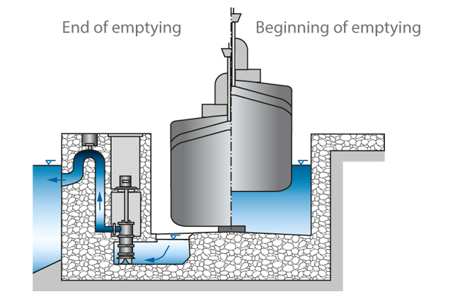
See Fig. 1 Dock pump

The pump installation of a graving dock is commonly located on one of the longitudinal sides, near the dock gate. The water enters the intake chamber via the dock floor and is then evenly distributed to the bilge pumps (usually between two and four pumps).
When pumping commences, the geodetic head equals zero. Only the pipe friction losses and the discharge loss have to be overcome. Due to the large suction head of 10 to 12 m the NPSH value of the pump is generally unproblematic.
As the water level in the dock sinks progressively, the head of the system rises and the flow rate of the pump decreases (see Characteristic curve).
Towards the end of the draining process the bilge pumps are stopped one after the other, and smaller tubular casing pumps with a diffuser (after-bilge pumps, see Mixed flow pump) are started up.
When the dock is completely empty, drainage pumps are employed for draining any leakage water. As coarse contamination of the leakage water caused by repair work in the docks has to be expected, such drainage pumps are often fitted with channel impellers (see Impeller).
Pumps for floating drydocks
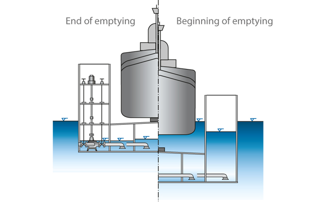
See Fig. 2 Dock pump

In a floating drydock the bilge pumps (usually four to six pumps, or more if required) are installed in one of the legs of the U-shaped floating structure. These pumps are vertically installed. They are usually double-suction pumps of radially split design with annular or volute casing suitable for flow rates from approximately 500 to 3500 m3/h.
The rotating assembly can be pulled out from the top. The pump shaft and the exposed drive shaft, which extends vertically upwards, are supported by grease-lubricated plain bearings. The thrust bearing and the drive are arranged in a water-tight chamber some metres above the pump.
The complete floating drydock is divided into chambers, which can be flooded individually. When the dock is submerged (flooded) the pumps and drive shafts are also submerged (see Wet well installation). Each chamber is equipped with its own suction line, which is connected to the corresponding bilge pump via a shut-off valve (see Valve).
The pumps and shut-off valves can be operated from a control station, from where the water levels of each chamber as well as the longitudinal and transverse inclination of the dock can be monitored. To lift the dock and the docked vessel the amounts of water which are pumped off from the individual chambers may vary to accommodate the weight distribution. In contrast to graving docks, the head of this installation fluctuates by no more than a few metres.