M

Mag-drive pump

Mag-drive pumps are seal-less pumps whose shaft torque is transmitted via a magnetic coupling drive (see Magnetic coupling) with permanent magnets by means of magnetic induction.

To prevent any leakage to atmosphere through a containment shroud failure during operation, mag-drive pumps are sometimes designed with double-walled containment shrouds and a leakage monitor. See Fig. 3 Chemical pump


Magnetic coupling

A magnetic coupling can be used to transfer power to centrifugal pumps. It consists of a primary part which is rigidly connected to the motor shaft, and a secondary part which is arranged on a shaft (see Pump shaft) together with the impeller

Both the primary and the secondary parts are fitted with permanent magnets. Poles of opposite polarity face each other. They attract each other due to the magnetic flux. When the primary part is driven, the secondary part rotates synchronously (at the same rotational speed). 

Centrifugal pumps with magnetic couplings are also referred to as mag-drive pumps magnetic drive pumps or magnetic pumps. These days they can be designed with power ratings as high as 400 kW.
See Fig. 1 Magnetic coupling

This is an embedded image

When the torque, to be transmitted increases, the angular displacement or load angle between the axes of the magnets of the primary part and the secondary part will also increase. If the torque to be transmitted exceeds a given maximum value (decoupling torque), the coupling will break out of sync and the secondary part will come to a standstill. In this case, the drive must be switched off as run-up requires the two parts to be in synchronisation.

This disadvantage can generally be ignored for centrifugal pump sets with a suitable drive rating. It can be avoided altogether by using a secondary part which is designed like the squirrel-cage rotor of an asynchronous motor. This design allows for asynchronous run-up and operation.

A partition (occasionally a double partition for safety reasons) is fitted in the gap between the primary part and the secondary part of the magnetic coupling (double-walled containment shell) and seals the pump hermetically. For this reason, the applications centrifugal mag-drive pumps are used for are similar to those of canned motor pumps. See Fig. 3 Chemical pump

Magnetic couplings must not be confused with the electromagnetic clutches used for control purposes or for protection against shock loading.

Mains voltage

The mains voltage is the electrical voltage supplied by utility companies via the power grid to transmit electrical power. Mains voltage can be realised as low or high voltage, depending on the power transmitted, whereby the latter subdivides into medium, high, and maximum voltage.

Low voltage

  • As three-phase current as well as alternating voltage (up to 1,000 volts), and direct voltage (up to 1,500 volts) 

High voltage

  • Over 1,000 volts (1 kV), typically for low-loss transmission of electrical energy
  • Further subdivision into medium voltage (3, 6, 10, 15, 20, 30 kV in industrial enterprises and towns), high voltage (60 kV, 110 kV in cities and smaller power stations), and maximum voltage (220, 380, 500, 700 kV for meeting the requirements of major metropolitan areas and large power stations)

Maintenance

Maintenance refers to checks, inspection and care required to be regularly performed in defined intervals during service life. The maintenance schedule and scope are specified in the operating manual. Maintenance contracts are often provided on a product-related basis.

Regular maintenance of pumps and drives prolongs their service life and saves costs. The related work includes the outside upkeep of pumps and pump sets, maintenance of bearings and shaft seals, as well as like work, e.g. inspection

Outside upkeep of pumps and pump sets 

Pump sets must be cleaned on the outside at regular intervals depending on the degree of contamination. When doing so, the pumps and motors must never be hosed down.
Rusty spots must be removed and treated accordingly, while preservative grease must be applied on exposed parts. 

Bearing maintenance

Bearings must be maintained on a regular basis since lubricants use up at different time intervals. Operators need to either replace or top them up (e.g. by changing the oil, refilling the oil, or replacing the grease altogether). The operating manual specifies the intervals as well as lubricants and their quality.

Shaft seal maintenance

Shaft seal maintenance depends on the design variant used. There are gland packings and mechanical seals. 


Seals are maintained depending on their design

  • It is imperative that gland packings drip slightly during operation. Fully sealing gland packings will cause damage to parts such as the shaft or the shaft protecting sleeve. In this case, the nuts of the gland packing bolts are loosened until the gland packing starts dripping slightly. This also applies to metal, ring and soft plastic packings.
  • In most cases, leakage of mechanical seals is not visible from the outside. This means that no special maintenance is required. However, if there are larger amounts of leakage, the sealing elements must be replaced. More details are given in the operating manual.

Other maintenance 

To provide additional information, it is recommended to have the operating personnel take part in inspections. In this case, maintenance is often performed following a checklist. 

Inspection and maintenance performed by the operating personnel 

  • Checking the smooth running of the centrifugal pump and drive
  • Checking the motor rating taking the power input into account
  • Checking the coupling alignment (see shaft coupling
  • Checking the flexible transmission elements for wear (e.g. at coupling disc, coupling bolt and coupling bushes)
  • Checking the flushing and barrier water supply systems
  • Checking the balancing device if any (e.g. at the balance disc)
  • Functional testing of the automatic grease presses (e.g. lubricating oil pump) and grease lines, if any

Example of a checklist

  • Checking the smooth running of pump and drive
  • Checking the performance data taking the power input into account
  • Checking the oil and/or grease lubrication (of the bearings)
  • Checking the shaft seals (e.g. gland packing, mechanical seal, lip seals) and, if needed, re-packing the glands, or, in the case of mechanical seals, replacing the rotating and stationary primary rings
  • Checking the coupling alignment
  • Checking the flexible transmission elements for wear
  • Functional checks of shut-off elements and check valves
  • Checking the system and its components for corrosion (for example, along the outer surfaces) or for cavitation and erosion damage of internal pump parts
  • Determining the spare parts requirements
  • Checking the flushing and barrier water supply systems, if any
  • Cleaning the solenoid valves, if any
  • Checking the balancing devices, if any
  • Checking the electro-pneumatic control systems (only for waste water pumps)
  • Functional testing of the automatic grease presses and grease lines, if any
  • Checking for wear of waste water pumps via the handhole cover, if any
  • Measuring the rotor clearance
  • Checking the clearances
  • Performing a test run after maintenance

Maintenance contract

In technical language, a maintenance contract is also referred to as an inspection contract. It is product-specific so that the intervals, scope of services and commercial terms and conditions can be defined between the customer and the contractor (see also servicing).

Manufacturer's Declaration

In accordance with the revised version of the Machinery Directive (2006/42/EC) dated May 2006 a Declaration of Incorporation was introduced as a legally binding replacement for the Manufacturer's Declaration with effect from 29 December 2009. This declaration must include information stating that machinery must not be put into service until all the components have been declared in conformity with the Directive.

Manufacturing tolerance

The manufacturing tolerance is the level of deviation from the values guaranteed in the acceptance test that is permitted and which occurs as a result of imprecision when manufacturing the hydraulic pump components. It includes profile defects, surface factors and assembly differences, as well as all factors arising from differences between the prototype version and subsequent reproductions (e.g. the series).

The manufacturing tolerance affects the pump operating data (e.g flow rate, head) and is determined by the pump production method. It must be taken into account, for example, when carrying out a characteristic curve comparison between the catalogue values (possibly also guaranteed values) and the measurement results for a real pump. Measurement errors may even occur when tests are merely repeated without making any changes to the pump.

Acceptance standard DIN EN ISO 9906 for centrifugal pumps does not refer to the manufacturing tolerance specifically. However, it is taken into account as part of the tolerance factors in the form of a certain allowance for measurement uncertainty.

Marine pump

"Marine pump" is a collective term for all pumps complying with the relevant regulations issued by the shipbuilding classification societies.

Marine pumps designed as centrifugal pumps perform a great variety of duties on board (see Pump application): in the engine room as a boiler feed pump, condensate pump and cooling water pump using seawater or fresh water, in the bow as a transverse thruster in special pump rooms as a cargo oil pump, Butterworth pump or ballast pump, for special duties as an antirolling, antiheel or trimming pump, as a bilge pump, or stripping pump, as a fire-fighting pump and as a service pump for a variety of applications. Dock pumps are also classified as marine pumps. Cooling water pumps using either seawater or fresh water (e.g. seawater pump) and fire-fighting pumps draw in fluid from the sea chests via suction lines. Sea chests are tanks mounted to the inner side of the ship's hull below the water line. Their apertures face seawards and are covered by inlet screens.

If the fluid handled is seawater, suitable pump material is required: gunmetal or bronze (e.g. multi-alloy aluminium bronze) for the pump casing and impeller and chrome nickel steel for the pump shaft

As bilge and ballast water lines often require large quantities of air to be evacuated, many of the pumps on board are self-priming pumps. They are water ring pumps which rotate continuously with the main pump. Separate bleeding devices (see Venting) such as ejectors or central vacuum systems are also gaining in popularity.

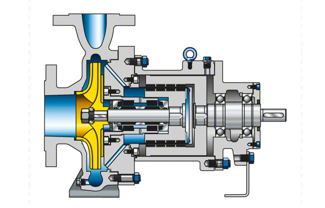
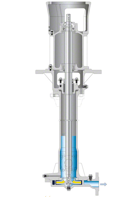
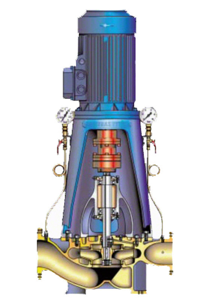
Due to the restricted installation space on board the most suitable design for the majority of marine pumps is a vertical pump in radially split) design with the motor mounted directly on top. See Fig. 1 Marine pump

This is an embedded image

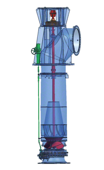
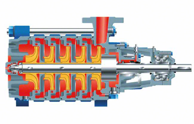
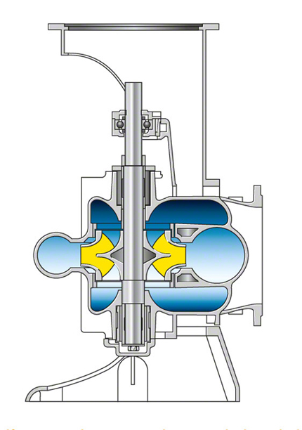
In some individual cases, axially split designs are used. See Fig. 2 Marine pump

This is an embedded image

The flow rates of vertical, radially split marine pumps range from 30 to 1200 m3/h at heads of 15 to 125 m. Single-entry impellers are fitted for low flow rates and double-entry impellers (see Double-suction pump) for high flow rates. The pump shaft is guided in grease-packed rolling element bearings arranged outside the pump casing.

For inspection and repair purposes the rotating assembly can easily be lifted out upwards after removal of the coupling spacer sleeve (see Shaft coupling) The motor need not be removed, and the pump casing can remain installed on the pump foundation

Axially split, vertical marine pumps are used for flow rates from 1,000 to 5,000 m3/h and heads of 15 to 85 m.

The pump shaft is guided in a grease-packed rolling element bearing below the shaft coupling and in a product-lubricated plain bearing below the impeller.

The front part of the casing has to be removed sideways before the pump rotor can be dismantled. See Fig. 2 Marine pump

On turbine ships equipped with large boiler plants and correspondingly large condensers, double-suction centrifugal pumps are used for cooling water supply. Because of the low heads involved, propeller pumps with an axially split casing are also sometimes adopted.

Marine condensate pumps have to able to operate at extremely low inlet heads. The first stage impeller (see Suction stage impeller) is a special impeller arranged at the bottom. The flow approaches it from underneath. To improve the NPSHR value inducers can be installed. The bearings are arranged outside of the fluid handled.

Marine condensate pumps generate flow rates ranging from 5 to 250 m3/h and heads of 30 to 140 m.


Mass flow rate

The mass flow rate (m · ) is the rate at which mass flows through a reference cross-section per unit of time. For centrifugal pumps, this is defined as the massflow rate pumped through the outlet cross-section and any tapping cross-sections of the pump with respect to this unit of time.

This is an embedded image

The SI unit of measurement for the mass flow rate is kilograms per second (kg/s).

Other common units of measurement for centrifugal pumps include kg/h and t/h.

Master/slave mode

The master/slave mode is used for hierarchically managing the access rights of common resources in a communications system. In decentral bus-controlled systems, for instance, an automation device (master) grants access rights for the other components (slaves). See Fig. 1 Master/slave mode

This is an embedded image


Material

Of the multitude of available materials, metallic and non-metallic (such as plastic and ceramic) materials are preferred for centrifugal pumps, although the exact choice depends on the level of stress involved.

Metallic material

Metallic materials take the form of cast materials, forged or rolled materials, or materials in some other product form. Given the high level of freedom that is available in terms of design and the wide array of special alloy types, these remain the most frequently used design materials for pump casings and impellers.

The cast materials used in centrifugal pumps vary depending on the desired material composition and the mechanical and technological properties required. See Fig 1 Material

Plastics

Plastics are divided into four groups according to the ISO 1043-1 standard, based on how their mechanical response to temperature is.

Mechanical behaviour of the four plastic groups

  • Thermoplastics:
    When subjected to heat, these materials can be deformed any number of times. Examples include polystyrene (PS), polyethylene (PE) and polyvinyl chloride (PVC).
  • Elastomers:
    These are wide-mesh cross-linked high-polymer materials with rubber-like elastic properties in all temperature ranges (e.g. cross-linked natural rubber or polyisobutylene).
  • Thermoplastic elastomers:
    These materials are wide-mesh cross-linked high-polymer materials that attain rubber-like elastic properties at temperatures above 20 °C, e.g. natural rubber crosslinked with more than 10 %sulphur, cross-linked polyethylene or high molecular weight polymethyl methacrylate (PMMA).
  • Thermosets:
    These close-mesh cross-linked substances are cured high-polymer materials (e.g. polyester, epoxy or phenol formaldehyde resins).

Thermoplastics have a particularly important role to play as design materials for impellers and diffusers whereas elastomers are used for sealing elements or as coating materials.
See Fig. 2 Material

Ceramic materials

Ceramic materials are defined as materials that are non-metallic, inorganic and more than 30 % crystalline. They are used not only as state-ofthe-art engineering ceramics for sealing and bearing elements (see plain bearing) but also increasingly for other design elements, such as impeller wear rings and casing wear rings (see controlled gap seal) as well as impellers.

See Fig. 3 Material

This is an embedded image

This group of materials is characterised by its high mechanical, thermal and chemical stability. As well as being brittle and sensitive to tensile stress, these materials can only be formed to a limited extent and are expensive to process. Therefore, the designs have to take account of their properties.

Material selection

When selecting the material for certain pump components, it is particularly important to have a precise understanding of the collective load profile as well as a thorough familiarity with the product type. This includes static and dynamic stresses of a mechanical and thermal nature as well as stress caused by erosion, abrasion, corrosion and cavitation. The question of which types of stress constitute decisive criteria when selecting materials can essentially only be answered by someone who has many years' experience in a wide range of pump applications.

General material selection tables are available for specific types of stress. These can serve as a basic guide for determining pump materials. One of the most commonly known formats is the chemical resistance table, which lists (usually metallic) materials according to their level of corrosion resistance to liquid media.

In addition to the product form and the stress collective, financial aspects also play a key role in material selection for many applications. By contrast, in special applications such as a reactor pump for nuclear plants, the only criteria that count are those that relate to safety.

Given that pump manufacturing now relies heavily on computers, issues such as processability, availability and purchasibility are also significant factors when selecting materials.

Ultimately, the process of selecting materials for a pump component and a particular application is bound up with the expertise and responsibilities of the pump manufacturer. There is therefore often a great deal of variation between specific manufacturers.

Measurand

The measurand, or measured quantity, is the physical quantity in metrology, subject to measurement. The term is used for a measured quantity in the general sense as well as a particular quantity.

A measurand in the general sense refers to a physical quantity that was or will be subject to measurement, e.g. mass, power or temperature.

A particular quantity is a (derived) quantity describing a specific physical characteristic, e.g. the volume of a body or the resistance of a copper wire at a given temperature.

The measurand does not need to be measured directly; it can also be indirectly determined by means of known physical or specified mathematical relationships from between the various quantities (measured values) under measurement.

A distinction is made between dimensionless measurands such as the angle, whose values are measured directly as rational numbers, and dimensioned measurands such as density, whose values are comparable to the values of the same dimension. This comparability is expressed by specifying the value of a dimensioned measurand as a multiple of the relevant measurement unit.

Measurement accuracy

In metrology, it is generally not possible to take error-free measurements, since many factors prevent the measurand from being measured correctly. Measurement accuracy describes the closeness of agreement between the measured value and the true value of the measurand. This accuracy does not represent an absolute specification, but a relative deviation with respect to a traceable calibration standard.

Measurement error

Measurement errors, or errors of measurement, are also referred to measurement deviations. Measurement errors are used in metrology and represent the difference between the measured value indicated minus the correct (true) value as per DIN standard 1319.

The indicated value (measurement result) is skewed by imperfections in the measuring instruments and measuring methods (systematic error (fsys)) and by environmental influences as well as change over time for all measurands (random error (fr)).

The geometric sum (root of the sum of squares) of both measurement errors yields the total error (ftot). This error, which occurs in (acceptance) measurements, is regarded in acceptance standard DIN EN ISO 9906:2012 via specification of permissible total measurement uncertainties that are changed following the current revision of DIN EN ISO 9906:2012 . See Fig. 1 Measurement error

This is an embedded image

Changed, permissible total measurement uncertainties are described in a revision of this standard that has not yet been published. See Fig. 2 Measurement error

This is an embedded image


Measurement uncertainty

Measurement uncertainty as defined by DIN 1319, page 3, encompasses the random errors of all individual quantities from which the measurement result is calculated and errors that are not recorded because they cannot be quantified and thus represent estimated, systematic errors. It is relevant to metrology applications. 

The systematic measurement uncertainty of individual measurement methods and measuring instruments must be determined using information provided by the manufacturers of the measuring instruments. These devices must be calibrated as required, whereby systematic measurement uncertainty can be reduced to that of the calibration unit.

Every measurement taken is inextricably subject to measurement uncertainty, even if the measurement methods, devices, and evaluation requirements fully comply with the relevant acceptance test codes.

When the test results are compared to the guaranteed values, the measurement uncertainty must be suitably taken into account in a way that is not influenced by the pump and the guaranteed values (see EN ISO DIN 9906).

If the characteristic value of a pump, such as the head, is calculated from several (different) measurands, the measurement uncertainty for these must be determined by geometric addition (root of the sum of squares) of the measurement uncertainties of the individual quantities:

This is an embedded image

Measurement uncertainty is determined in a similar manner when a value calculated from different measured values is assessed. Efficiency, for example, primarily comprises the measurement results for the flow rate, head, and pump input power, the measurement uncertainties of which determine that of efficiency.

This is an embedded image

Defined total measurement uncertainties can be used if no special tolerance values are provided by the device manufacturers. See Figs. 1, 2 Measurement error

Measuring instrument

The measuring instrument provides the measured value of a measurand and is used in metrology applications.

Every measuring instrument has a specific output or indication range in which information is provided about the measurand.

Important and proven measuring methods and measuring equipment (measuring instruments) in centrifugal pump technology:


Measuring range

The measuring range is the range of measured values for a measurand, in which defined, agreed, or guaranteed error limits are not exceeded. It is delimited by a lower and an upper measuring range limit that define the measuring span. Measured values are used in metrology.

The output or indication range of a measuring instrument frequently, but not always, coincides with the measuring range.

Measuring range limit

The measuring range limit is frequently the reference value for calculating the error limit from the class index if an accuracy class is used as a basis.

Measuring transducer

A measuring transducer is a measuring instrument (also see Sensor) that incorporates ready-to-use electronics in addition to on-board sensors and provides an output quantity having a specified relation to the input quantity as per basic standard DIN 1319. The term transmitter is also used as for the pressure or level transmitter.

Many different physical quantities are used as input signals. The element of the measuring equipment that is directly affected by the measurand is known as the pick-up or sensor (as per DIN 1319). As output signals, the quantities frequently produce a standardised analog electric signal such as 0 - 20 mA, 4 - 20 mA, or 0 - 10 V, but can also have a digital signal structure.

These measuring transducers typically offer galvanic isolation for measurand and output quantity.

Mechanical efficiency

Mechanical efficiency (ηm) is described as the ratio between the power input (P) minus the mechanical power loss (PL.m) and the power input itself:

This is an embedded image

Power loss refers primarily to the friction loss in pump bearings (e.g. plain and rolling element bearings) and shaft seals.

It typically consumes 0.5 to 2 % of power input, whereby this figure generally becomes smaller the more powerful the centrifugal pump.

Mechanical power

Mechanical power (P) is the quotient of mechanical work (A) by time (t). The SI unit of measurement is watts (W).

Mechanical work (A) is performed when a force (F) causes movement in time (s) in the direction of the force applied.

This is an embedded image

With respect to rotational movement, mechanical power is the product of torque (T) and angular velocity (ω) (see Rotational speed). 

This is an embedded image


Mechatronics

Mechatronics encompasses mechanical, electronic, and IT-related components. The term is derived from mechanics, electronics and informatics.

Mercury pump

A mercury pump transports mercury in chlor-alkali electrolysis processes based on the mercury cell method. In this process, a layer of mercury flowing across the bottom of the electrolytic cell serves as the cathode, which is where an amalgam is formed. In a second cell a decomposer transforms the amalgam into mercury, an alkaline and hydrogen. The mercury is then returned to the electrolytic cell by the mercury pump.

Most mercury pumps are vertical, dry-installed centrifugal pumps, which are mounted on the side of the electrolytic cell or the decomposer. They are positioned for the mercury level above the upward-facing impeller inlet to be kept as low as possible.

The pump shaft with overhung impeller is supported by grease-packed rolling element bearings and designed for uncritical operation. The shaft seal is not in contact with the fluid handled. It is a gland packing arranged in the support column at a suitable distance above the mercury level. It is often supplied with barrier water and serves to prevent any leakage of water polluted with mercury as well as any ingress of dirt. Using double mechanical seals supplied with barrier water prevents any leakage of mercury at the shaft seal. Using seal-less canned motor pumps ensures leakage-free operation. See Fig. 1 Mercury pump

This is an embedded image


MES

MES stands for Manufacturing Execution System. In a production control system, this term refers to the technical data connection between the commercial level of a company and production. The purpose of an MES is to improve transparency, reduce costs, and increase throughput and quality.

Metrology

Metrology encompasses all measures for determining the status of physical quantities and leverages measuring instruments and methods for quantifying (measuring) physical quantities such as length, weight, force, pressure, current, temperature, and time.

Heightened technical and economic requirements for developing, manufacturing, and operating centrifugal pumps make it increasingly necessary to quantify physical states and quantities, thus enhancing the scope of measurement tasks. This also applies to measuring instruments as used for monitoring and closed-loop control purposes, whereby conventional measuring tasks are carried out via improved methods as new methods are added.

Electric and electronic measurement methods are increasingly being used and have already established themselves as irreplaceable in many areas.

Current technical developments are characterised by their application of electric (digital) measured value transmission for multi-value measuring equipment and data-processing facilities.

Important sub-areas of metrology are the development of measuring systems and measurement methods and the processes of recording, modelling, and reducing (correcting) measurement errors and undesired influences. This also includes the adjustment and calibration of measuring instruments. Metrology is required for automation in conjunction with open-loop and closed-loop control systems.

 Important terms for taking a measurement:


MIF

MIF stands for "Magnetic-Inductive Flow Measurement" and is also referred to as "Inductive Flow Measurement" (IFM). MIF describes a measuring principle of a sensor, whereby an electrically relevant signal is generated from a flow rate. To this end, the charge carriers in a liquid are diverted by a magnetic field, thus generating a voltage.

Miniature circuit breaker

A miniature circuit breaker is an overcurrent protective device. It protects an electrical circuit from being damaged, e.g. by excessive heat resulting from excess current. Miniature circuit breakers can be reset after they have been tripped and thus, unlike fuses, do not have to be replaced.

Minimum flow rate

The minimum flow rate describes the lowest possible flow rate, to be maintained in order to prevent impermissible increases in temperature inside the pump. The minimum flow valve arranged behind a boiler feed pump for example, maintains this rate. See Fig. 5 Valve

Mixed flow

The term "mixed flow" describes a direction that is halfway between axial (along the axis) and radial (perpendicular to the axis). In the case of centrifugal pumps, the term "mixed flow" means that the fluid flowing in the impeller gets transported in a semi-axial direction.

Mixed flow pump

A mixed flow pump is a centrifugal pump with a mixed flow impeller. The specific speeds (ns) lie between 35 and 80 rpm for low-speed mixed flow pumps, and between 80 and 160 rpm for higher-speed mixed flow pumps (in special cases even higher). Mixed flow pumps cover the transition range between  radial flow pumps and axial flow pumps (e.g. propeller pumps). 

The impellers of mixed flow pumps with a low specific speed are combined with an annular or volute casing; those of mixed flow pumps with a higher specific speed are combined with a diffuser and a tubular casing.

See Fig. 1 Mixed flow pump

This is an embedded image

The optimum specific speed range for tubular casing mixed flow pumps with regard to construction costs and efficiency is not clearly defined. However, from approximately 130 rpm upwards, the tangential component of the absolute velocity at the impeller outlet becomes so small in comparison with the flow velocity at the pump suction nozzle that the end cross-sections of the volute or annular casing required to convey the flow (see Flow rate) would become disproportionately large. In such cases the mixed flow pumps would have to be designed with an excessively large radial casing, which would possibly still be viable if made of concrete but very expensive if made of cast iron or steel. See Fig. 6 Cooling water pump

For this reason, mixed flow pumps with higher specific speeds are usually designed with an axial tubular casing and an "onion type" or axial flow diffuser through which the fluid flows towards the discharge elbow and the pump discharge nozzle

The range of heads of mixed flow pumps with tubular casing complements that of the propeller pump at the top end of the head range. As the circumferential velocity of a mixed flow impeller is restricted to 25 to 30 m/s to prevent cavitation (see Suction characteristics) the mixed flow pump can only exceed its maximum head of H = 60 m if it is designed as a multistage pump. In practice, the number of stages is limited to two or three.

As the impeller geometry of mixed flow pumps, unlike that of propeller pumps, does not allow closed-loop control by means of impeller blade pitch controlpre-swirl control is recommended. Pre-swirl control is effected by means of a cardan shaft connected to a rod structure leading above floor level outside the tubular casing. See Fig. 2 Mixed flow pump and Fig.10 Cooling water pump

This is an embedded image

In the case of multistage mixed flow pumps with tubular casing, pre-swirl control devices can be applied upstream of each individual impeller at every stage. In many cases, however, the overall control effect of a single pre-swirl control device fitted upstream of the first stage is sufficient.

If the fluid handled is clean and the heads are no higher than 15 m, it is unnecessary to fit a front shroud on mixed flow impellers (see Open impeller). For higher heads, closed impellers are recommended in order to reduce clearance gap losses (see Clearance gap width).

Mixer

Mixers are blending devices used in process engineering. Mixers consist of the following components: propeller, submersible motor and installation accessories. See Fig. 1 Submersible mixer

Other mixer types are driven by dry-installed standard motors and medium-exposed shafts.
Mixers are used for homogenising, emulsifying, dispersing, suspending and flow generation.

Main hydraulic tasks

  • Introducing and mixing various gases, liquids or solid substances into a fluid
  • Preventing conglomeration of sludge flakes
  • Circulating phase mixtures
  • Preventing sedimentation (in the case of insufficient fluid flow velocity in the tank)
  • Aligning the mixer to break up floating sludge layers

The applications and wide range of hydraulic tasks to be fulfilled by mixers entail different requirements for these machines. Assessment criteria include propeller diameters, thrust and the thrust/power ratio to ISO 21630.

Mixers are designed for stationary installation on the tank floor or tank wall, or for pedestal mounting. Specific propeller orientation helps create a circumferential flow. If required, several mixers should be installed in a tank.

Mixers are sealed to prevent ingress of water and come either in a close-coupled design or with gear unit They are driven by three-phase asynchronous motors which are safe to run dry. The bearings used are maintenance-free rolling element bearingsMechanical seals are used for sealing on both the product side and the drive end.

The propellers are designed with fibre-repellent, self-cleaning blades with backward curved incidence edges and are made of grey cast iron, stainless steel or a synthetic material depending on the fluid to be handled.

Mixers are installed via a guide bracket fitted to the mixer; it allows the submersible mixer to be lowered into the tank along a guide rail. The positioning of the mixer (including installation accessories) is performed in such a way that it is correctly orientated before being lowered into its working position in a mounting bracket. Appropriately designed installation equipment ensures that the forces developing during operation are transmitted to the tank floor.

A mixer can be withdrawn from the tank for repair and maintenance work at any time.

Model Testing

In cases where technical or economic factors (for example size, rotational speed and material/fluid properties) make testing on an object or process infeasible under original conditions, measurements can also be made by means of model testing.

Particularly in the case of hydraulic turbomachinery (centrifugal pumps, water turbines, hydraulic torque converters) model testing can be conducted:

  • on reduced scale models,
  • and/or with reduced rotational speed,
  • and using a substitute fluid as appropriate.

The advantages of model testing are:

  • reduced dimensions of the test object and the test facility,
  • lower power input/operating costs during testing,
  • potentially easier handling of the fluid (e.g. cold water instead of hot water or toxic, flammable fluids),
  • greater precision when transferring the results of highly precise model testing than when working with measurements taken under original conditions in the system.

When planning, performing and evaluating model tests and transferring the results to the original-size machine and/or the original operating conditions, the affinity laws must be observed and applied. Key considerations are:

  • Geometric similarity must be maintained, including clearance gap widths, and, where possible, surface roughness. Changes in length due to elastic and thermal deformations must also be observed.
  • Test results must be converted on the basis of model laws.
  • Dynamic similarity cannot usually be fulfilled. If infringement is unavoidable, apply corrections to the converted results, e.g. efficiency scale-up in cases where the Reynolds number equivalence is comprised in model testing and original conditions.
  • Cavitation model testing: observe the fluid properties (germ count, gas content).

Moment of inertia

The moment of inertia (J) is often used instead of moment of gyration (mD2). The unit kg/m² is used for both:

This is an embedded image

Thus, for the moment of inertia (J) relating to a rotational axis going through the centre of the circle, which is perpendicular to the circle plane:

This is an embedded image


Monitoring

Monitoring involves detecting the condition of components, e.g. within the context of process engineering. The aim is to regulate the processes by means of process control in cases where the processes being monitored do not run as required or where threshold values are undershot or exceeded.

Pump monitoring plays a key role in this context.

Motion Control

Motion control refers to the process of controlling drives to coordinate movements in a machine or plant.

Motor protection

Motor protection is the collective term used for all measures designed to protect electric motors and includes overload, short circuit, undervoltage and phase failure protection.

Motor protection protects electric motors from thermal overloading due to mechanical overloading or failure of individual phases.

An electric motor can be protected from an overload by monitoring its current requirement via motor protection switches or motor protection relays and by monitoring the temperature in the motor windings via bimetal switches and PTC resistors.

Motor protection relay

The motor protection relay is also referred to as overload relay and operates on the same principle as the motor protection switch. The motor does not directly trip automatically, however.

When an overload relay trips, for example, smaller (auxiliary) contacts that typically control a contactor (electronic switch) are switched. The contactor then trips the consumer. An overload relay does not have a short-circuit trip (short-circuit release). The thermal trip provided for this purpose (see bimetal) might respond too slowly in the event of a short circuit so that fuses must be fitted in the motor power cables to safeguard motor protection.

Motor protection switch

The motor protection switch protects a motor from overload and failure of an external conductor by monitoring current consumption. Motor protection switches used for three-phase motors typically integrate OR release logic in the three supply lines, which are monitored thermo-mechanically (bimetal), hermo-electronically (PTC resistor) or electronically (current measurement).

Restarting after tripping can take place automatically or manually by pressing a reset button.

Short-circuit trips, which are not actually required for motor protection, are also frequently installed to protect the power supply from short circuits. In accordance with DIN VDE 0100 they must be positioned at the start of a motor supply line.

Multistage pump

Multistage pumps are defined as pumps in which the fluid flows through several impellers fitted in series.

The head of a single-stage centrifugal pump is largely governed by the type of impeller and the circumferential speed. If the rotational speed cannot be increased due to other operating conditions and a larger impeller diameter would lead to very low specific speeds resulting in uneconomical efficiencies, fitting several stages in series (also see Series operation) can be an economic option of increasing the head. If the number of stages is altered at unchanged dimensions and speeds, the flow rate of such a multistage pump remains constant while the power input and head increase proportionally to the number of stages.

An example of a pump with several stage casings of the same type fitted in tandem arrangement is the ring-section pump. This type of pump is often used in power station applications, e.g. as a boiler feed pump and in industrial applications requiring high pressures.

The individual stages of a multistage pump do not necessarily have to be arranged in tandem. The balancing of axial thrust can be enhanced by arranging the stages back to back in pairs or groups (see Back-to-back impeller pump). A typical example would be the pipeline pump. Multistage pumps are an economic means of covering the higher pressure ranges of pump series selection charts Further advantages are that multistage pumps can easily be tapped downstream of a stage or that dummy stages can be fitted for future pressure increases.

A disadvantage of very large numbers of stages is the increasing sensitivity of the pump rotor to external or natural vibrations

Each stage consists of an impeller, a diffuser and return guide vanes), (usually combined with the diffuser), which are all located within one and the same stage casing.

Irrespective of the number of stages an inlet casing with radial or axial inlet nozzle is arranged upstream of the first stage, and the last stage is fitted in the discharge casing containing the balancing device and a shaft seal. Only the common pump shaft, tie bolts and baseplate have to be adjusted to accommodate the required number of stages. See Fig. 1 Multistage pump

This is an embedded image