To ensure trouble-free operation of a centrifugal pump the approach flow to the impeller must be disturbance-free and uniform.
While energy transfer from the vanes to the fluid handled is based on the centrifugal effect in the case of low specific speed radial flow pumps it is effected via flow deflection at the blades in the case of high specific speed propeller pumps. For this reason, pumps with higher specific speeds are more susceptible to disturbances in the approach flow than those with lower specific speeds.
Depending on the impeller type involved, the conditions for disturbance-free approach flow vary and must be strictly complied with. The three major criteria are absence of swirl, a uniform velocity distribution and absence of vortices
Absence of swirl
The swirl (see Vortex flow) at the impeller inlet represents a disturbance of the ideal approach flow to the impeller, unless it is deliberately used to control the head or improve the pump's suction characteristics (see Inducer) Vortex flows at the inlet cross-section of a pump in most cases are the result of asymmetries in the inlet (transverse approach flows, flows across an elbow, asymmetrical flow separation) or suction recirculation (see Operating behaviour).
If the direction of the tangential components at the pump's inlet cross-section coincides with the pump direction of rotation the swirl rotates in the same direction. As a swirl in the same direction of rotation as that of the pump increases (i.e. larger tangential components of the vortex flow), the head, pump input power and efficiency will decrease at constant flow rate. The reason is the reduced deflection performed by the impeller vanes in comparison with their design point capability.
If a swirl in the opposite direction to the pump's direction of rotation increases, the head will increase at constant flow rate to the point where the vanes are overloaded (flow separation at the suction side of the vane, mechanical vibrations). The pump's efficiency will however drop faster than in the case of a swirl in the same direction of rotation. In the case of a swirl in the opposite direction, the resultant additional pump input
power requirement may lead to drive overload.
The disturbance factor "swirl" in the approach flow is established via flow velocity measurements with regard to both magnitude and direction, using probes, hot wire or laser measurement equipment or (as often employed in modelling) a rotameter, i.e. a speed-monitored paddle wheel of the size of an impeller arranged in the suction nozzle.
The swirl can also be established using CFD analysis.
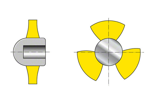
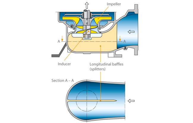
Honeycomb flow straighteners offer the best solution for reducing existing swirl components, but simple diffuser plates in the form of baffles, cruciform flow straighteners and centrally arranged longitudinal baffles (splitters) are also effective. See Fig. 1 to 3 Inlet conditions
On the basis of tests on pumps equipped with pre-swirl control (specific speeds ns of 70 to 200 rpm), tangential components of the flow velocity at the suction nozzle's outer edge which amount to less than 7 % of the corresponding axial components do not represent a major disturbance.
This corresponds to a swirl angle of approx. 4 degrees.
The percentage rate above must be reduced in the case of pumps with specific speeds exceeding 200 rpm due to the need to comply more strictly with the inlet conditions.
Complete absence of swirl at the pump's inlet is practically impossible to achieve.
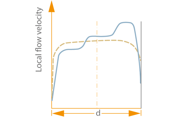
Uniform velocity distribution
When designing a pump impeller, a uniform velocity distribution in the cylindrical portion of the suction line is generally assumed. This is understood as comprising all the profiles of the axial flow velocities between the rectangular profile and the profile for fully developed turbulent flow in the pipe.
Distortions of the uniform velocity distribution pattern mainly occur as a result of flow around obstacles (wake depressions), and from any form of flow deviation and separation.
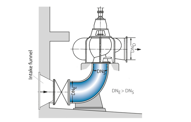
See Fig. 2 Intake elbow
The greater the deviation from uniform velocity distribution, the less likely it is that the pump can reach the required performance data as the individual vanes are exposed to an approach flow under low flow and overload conditions in the region of the velocity distortion.
If the non-uniformity of velocity distribution is not rotationally symmetric, mechanical vibrations will occur as a result of the transient flow along the vanes.
Obstacles in the shape of screens or perforated plates arranged uniformly across the flow cross-section, a straight length of piping.
or considerable acceleration via a nozzle of an appropriate length will have a stabilising effect on the distorted velocity distribution.
If such devices cause the NPSH of the system (NPSHa) to drop to an unacceptable level making cavitation more likely, the only effective (but often very expensive) remedy is to improve the hydraulic characteristics of the intake chamber. Widening of the intake space results in lower velocity peaks and lengthening it will reduce the wake depressions. Deflections and flows around obstacles should be avoided or their effects minimised.
Rotationally symmetric deviations of the axial velocity from the volumetric average by more than ± 10 % and non-rotationally symmetric deviations of the local axial velocity on a circular segment by more than ± 5 % are generally considered unacceptable. However, deviations of the order of ± 5 % in the case of pumps with a very high specific speed (ns > 200 rpm) may already prove to be unacceptably high.
Absence of vortices
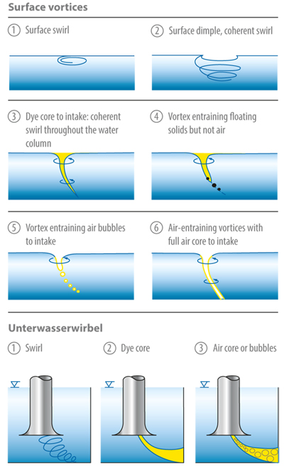
Vortices develop in shear flows and at locations with high gradients in the velocity profile. They may occur in the approach flow as a result of flow separation, deceleration, acceleration, branching off and a flow around installed structures. A differentiation is made between surface and submerged vortices; a more detailed presentation of different vortices is provided in the classification according to Hecker. Steam and gas may develop in the vortex core at a sufficiently high speed of rotation. See Fig. 4 Inlet conditions
Vortices which reach as far as the pump inlet impair the pump's performance data and operating behaviour. They include but are not limited to air-entraining surface vortices and air/gas-filled submerged vortices.
Swirl may lead to changes in the power, performance, head and flow rate. The vortices are often transient and, as a result of fluctuating pump performance, may in some cases be a cause of increased vibration and noise values which are associated with mechanical stress on the impeller or impeller vanes. Vortices' air and gas content additionally results in reduced performance data and lower efficiencies.
The most important prerequisite for disturbance-free continuous pump operation is the prevention of air-entraining vortices and air-/gas-laden submerged vortices. For this reason, surface vortices from type 3 and submerged vortices of types 2 and 3 (according to Hecker) are not acceptable for practical applications. Various measures can be taken to prevent air-entraining intake vortices (see Intake chamber).
Measures to be taken to prevent air-entraining vortices
- Improving the approach flow to avoid rotation and gradients in the velocity profile
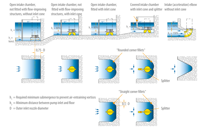
- Increasing submergence (h1) See Fig. 3 Inlet conditions
- Covering the suction water level vulnerable to air vortices by means of a raft
- Installing anti-vortex baffles in the region of suction water levels vulnerable to air vortices
Measures taken to prevent submerged vortices
- Improving the approach flow to avoid rotation and gradients in the velocity profile
- Using inlet cones with baffles see Fig. 1 Intake chamber
- Influencing the flow close to the respective walls by fitting anti-vortex vanes or similar structures
Standardised intake elbows and chambers optimised in model tests offer the best conditions for an approach flow that is as uniform and vortex-free as possible. See Fig. 3 Inlet conditions
In the case of pumps installed in pipes, the inlet line upstream of the pump should not have any turbulence-inducing structures. Elbows, valves and pipe branches may cause unacceptable inlet flow conditions for the pump. Several elbows installed one after another and/or elbows installed asymmetrically must be avoided. An unfavourable arrangement of these components may severely affect the pump's operating behaviour.
In the case of double-entry pumps, it is important to pay particular attention to the inlet conditions. When the flow leaving the elbow is asymmetrical (resulting from elbows installed asymmetrically), the impeller halves are not uniformly subjected to load, i.e. the impeller halves operate at different load points. In such cases, the negative impact on the NPSH value of the pump (NPSHr), the vibration behaviour and the load on the bearings may be much more pronounced than the effect on the pump characteristic curve.
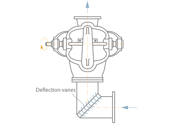
If sources of interference upstream of the pump cannot be avoided in the system, it is necessary to stabilise the inlet flow to an acceptable level.
This can be achieved by installing a sufficiently long, straight length of piping (approx. 5 to 8 times the nominal diameter DNs between the pump and the point of interference), elbows with a large radius, elbows with deflection vanes See Fig. 3 Inlet elbow and acceleration nozzles.
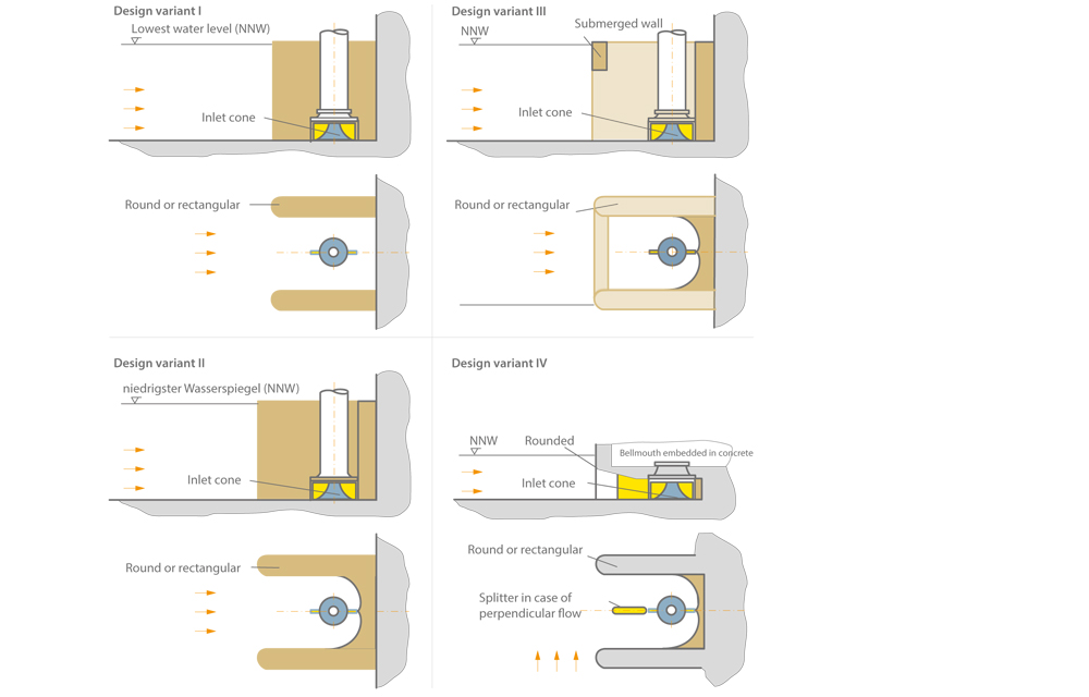
Disturbance-free approach flow examples
- The intake chamber design for a marine pump with inducer provides a relatively wide and long intake (deflection at low flow velocity). It is additionally equipped with a longitudinal baffle (splitter) to prevent larger swirl components. See Fig.1 Inlet conditions
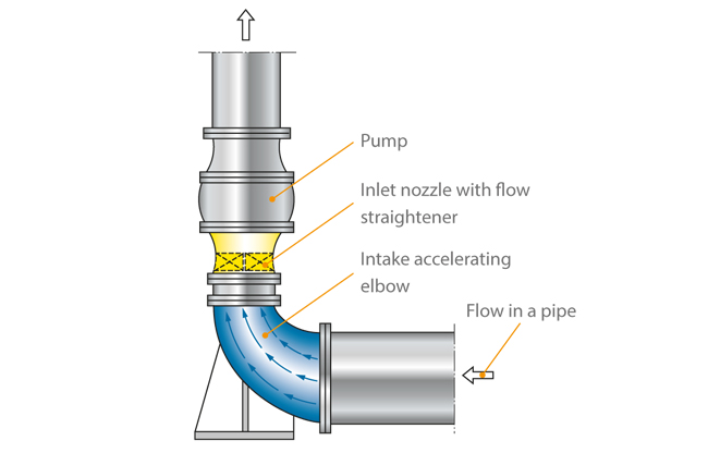
- Disturbance-free inlet flow in an intake elbow with circular cross-sections can be achieved if in the 90° deflection zone (elbow) the flow velocity is increased to approx. 2 to 4 times the pipe flow See Fig. 2 Inlet conditions . Accelerating elbows of this type are also successfully manufactured from concrete with adapter cross-sections from rectangular shapes to circles. See Fig. 6 Cooling water pump
- Recommended intake chamber designs for disturbance-free approach flows to vertical pumps are shown in Fig. 3 Inlet conditions. The covered intake chamber with inlet cone and splitter also allows cross flows to the pump, e.g. emergency operation in the event of a failure of associated travelling screens.