E

Earthing

The term earthing covers all earthing equipment and measures and how they are used to connect an electrically conductive part, such as the metal housing of electrical or electronic devices and equipment, to the earth.

Proper earthing ensures that potential differences between a device and the earth cannot occur in the event of a short circuit, overvoltage, or lightning strike, and protects both persons and equipment. There are two types of earthing: protective earthing and functional earthing.

Eccentric

The term "eccentric" describes the state of being off-centre or out of symmetry.

Economic efficiency

Economic efficiency is the ratio between the measurable increase in value and the expenditure required to achieve this increase. This concept is extremely important within the context of life cycle costs.

Eddy current sensor

When a conductive body is positioned in a magnetic field, eddy currents flow through this body due to the voltage induced in the conductive material. These eddy currents can be recorded via appropriate sensors. Eddy current sensors can measure the distances between and thicknesses of electrically conductive materials without making any physical contact.

Eductor-jet pump

Eductor-jet pumps are used if the water level on the suction side is too low for the suction lift operation of a normal pump. They transport fluids with relatively small flow rates of up to approximately 10 m3/h from narrow deep wells where the water level is up to 40 m below ground level (especially in the USA).

The advantage of this arrangement is that there are no moving components located in the deep well, so that no restrictions govern the installation of the centrifugal pump. The disadvantage is that the pump set has a lower overall efficiency than a borehole pump or submersible borehole pump

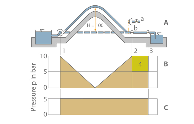
In an eductor-jet pump arrangement, a partial flow referred to as motive flow (QMo) is branched off from the total volume flow in the discharge line of an ordinary centrifugal pump installed above floor. The motive flow is recirculated to the eductor which is installed approximately 1 m beneath the lowest water level (see Water jet pump).

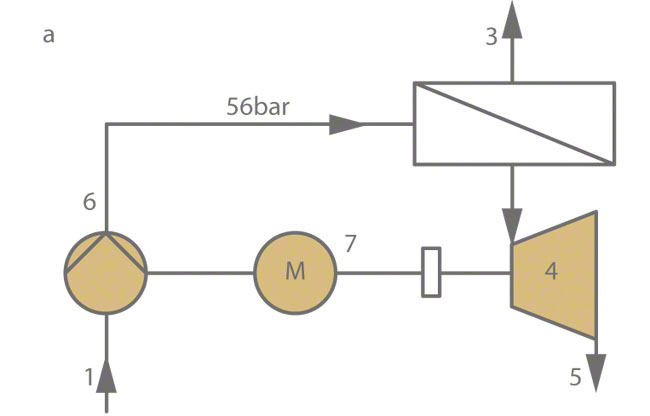
See Fig. 1 Eductor-jet pump

This is an embedded image

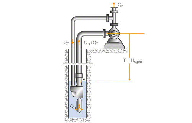
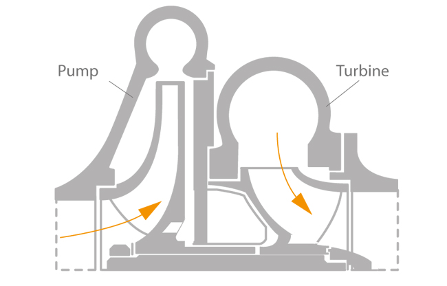
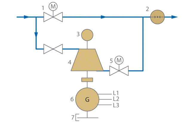
The eductor draws in the primary flow (QPr) and transports the total mixed fluid (QPr + QMo) to the pump suction nozzle. See Fig. 2 Eductor-jet pump

This is an embedded image

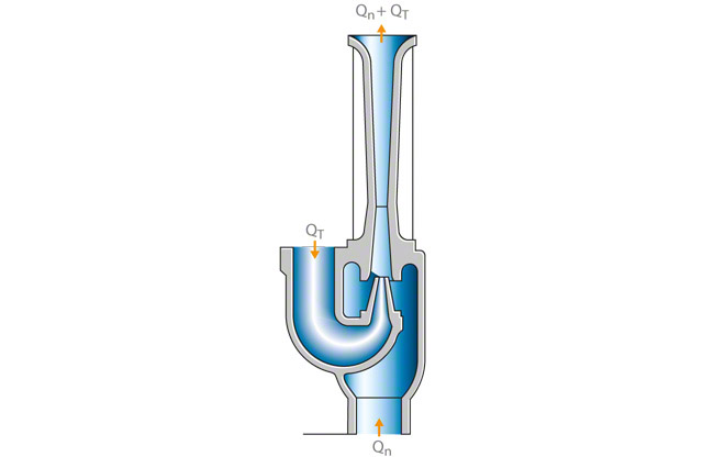
Once the fluid has passed through the pump, the same quantity of motive flow (QMo) is branched off again for recirculation. The primary flow (QPr) is supplied to the consumer installation.

The following equation applies:
HEff = WL + HLRiser - HS = WL + (HTotal + HMo) - HS

HTotal   Total head
HEff      Effective head of the eductor
HS        Permissible suction lift of the pump
HMo     Motive head
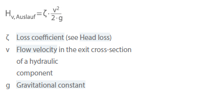
HLRiser Head loss in the riser pipe
HLMo   Head loss in the motive pipe
WL      Distance between water level and pump centreline
(Also see the numerical example below.)

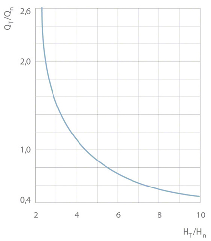
If approximate values are known for the distance between water level and pump centreline (WL) and the total head (HTotal), the effective head (HEff) and motive head (HMo) can be roughly determined. Then, the ratio of motive head and effective head (HMo/HEff) can be calculated. The corresponding ratio of motive flow to primary flow (QMo /QPr) can be obtained from the calculation diagram for eductor-jet pumps.

As the primary flow (QPr) is also given, both the motive flow  (QT) and the approximate design data of the centrifugal pump can be calculated.

See Fig. 3 Eductor-jet pump

This is an embedded image

When all data is known, a suitable pump type can be selected and the nominal diameter of the motive pipe and riser pipe can be determined. The data can then be used to calculate the values for the permissible suction lift (HS) as well as the head losses in the riser pipe (HLRiser) and motive pipe HLMo (see Pressure loss). The calculation can be repeated with more accurate values.


Numerical example

  • Given:
    HTotal = 80 m
    HLRiser = 4 m
    HS = 8 m
    QPr = 5 m3/h
    T = 20 m
  • Follows:
    HEff = WL + HLRiser – HS = (20 + 4 – 8) m = 16 m
    HMo = HTotal – HLRiser = (80 – 4) m = 76 m
    HMo / HEff = 76/16 = 4.75
  • Obtained from the diagram:
    See Fig. 3 Eductor-jet pump
    QMo / QPr = 0.95
  • Thus the flow rate of the motive fluid QMo of the eductor and the flow rate Q of the centrifugal pump equal:
    QMo = (QMo/QPr) · QPr = 0.95 · 5 m3/h = 4.75 m3/h
    Q = QPr + QMo = (5.0 + 4.75) m3/h
    Q = 9.75 m3/h


The head (H) of the centrifugal pump equals:

H = HTotal – HEff = (80 – 16) m

H = 64 m

The above values can be used to calculate the inside diameters and head losses of riser pipe and motive pipe. Then, the calculation can be repeated more accurately. In most cases the approximate calculation will be adequate.

For common eductor values the relationship of QMo / QPr and HMo / HEff is plotted in a curve. The exact curve depends on the type of eductor used. See Fig. 3 Eductor-jet pump

When planning to use a centrifugal pump in conjunction with an eductor-jet pump calculating the economic efficiency in detail is recommended, as eductors or water jet pumps have a relatively low efficiency compared with other suitable centrifugal pump types such as compared with other suitable centrifugal pump types such as borehole pumps, submersible motor pumps and submersible borehole pumps.

Efficiency

Efficiency (η) is generally understood as a ratio used to characterise the quality of power conversion in energy applications.

In particular in the case of "work-producing" machines (e.g. pumps, compressors, fans) and prime movers (e.g. turbines), efficiency describes the ratio of power input to power output, where the power output is the power input minus power losses:

This is an embedded image

In centrifugal pump engineering, the three terms (power output, power input and power loss) have different meanings depending on the type of efficiency being described in accordance with DIN EN ISO 17769-1. See Fig. 1 Efficiency

This is an embedded image

Pump efficiency η

Mechanical efficiency ηm

Internal efficiency ηi

  • Power output ... Pump power output (PQ)
  • Power input ... Pump input power (P) minus mechanical power loss (PL.m) in pump bearings and shaft seals

Hydraulic efficiency ηh

  • Power output ... Pump power output (PQ)
  • Power input ... Pump input power (P) minus power loss (PL,disc fric.) caused by disc friction and mechanical power loss (PL,m) in bearings and shaft seals

Pump set efficiency ηGr

  • Power output ... Pump power output (PQ)
  • Power input ... Drive input power, measured at a location to be agreed (e. g. terminal box of the electric motor, start of an underwater cable)

Efficiency class

All standard 2-pole and 4-pole low-voltage three-phase motors (e.g. asynchronous motor) with power ratings from 1 to 1000 kW are categorised in efficiency classes in accordance with their efficiency.

Four different classes have been defined: IE1, IE2, IE3 and IE4. IE4-classed motors have the best efficiency; this is the class for energy-saving or high-efficiency motors. Older motor models without efficiency specification are included in class IE1.
See Fig. 1 Efficiency class

This is an embedded image

The motor efficiency (η) is calculated on the basis of the ratio between the shaft output power (POUT) and the electrical input power (PIN). The difference results from internal motor losses.
See Fig. 2 Efficiency class

This is an embedded image


Efficiency scale-up

Efficiency scale-up takes account of the influence of the Reynolds number (Re number) on the pump's efficiency. When two geometrically similar centrifugal pumps are compared, either the larger one, the one with the higher speed or the one handling a fluid of lower viscosity usually exhibits a higher pump efficiency. This means that when transferring data established on a test model to a life-size prototype, the pump efficiency measured on the model must be scaled up. The pre-condition is however that geometrical similarity has been maintained in all components including surface roughness and clearance gap width (see Similarity conditions). 

Thus this change in efficiency is only a consequence of the change in the Reynolds number resulting from the change in pump size, rotational speed and viscosity.

Larger centrifugal pumps generally have higher Re numbers. According to the laws of fluid mechanics, these pumps exhibit lower flow losses within certain limits and therefore feature a higher internal efficiency.

As it is almost impossible to achieve exact geometrical similarity, it is important to take into account that the additional influence of the machine size has the same effect as that of the Re number. The influence of pump size on pump efficiency is of practical significance in all cases where efficiency measurements are performed on reduced scale models of larger pumps (see Pump test facility). This allows an evaluation of the anticipated efficiency of the life-size pump to obtain the pump input power, for instance, which would have exceeded the installed test facility power.

There are as yet no universally applicable rules for efficiency scale-up. In all cases, the efficiency scale-up method used must be clearly defined between user and manufacturer before the model test takes place. Examples of approximation equations for efficiency scale-up are those given by Pfleidererand Ackeret:

This is an embedded image

The Re number should be calculated on the basis of the circumferential speed of the impeller outlet diameter.

Practical examples for the use of efficiency scale-up equations are found in international standards: "Hydraulic Institute: Standards for centrifugal, rotary and reciprocating pumps. 14th ed, Cleveland 1983" and "IEC 497: International code for model acceptance tests of storage pumps. 1976" (12/2011 edition).

Elastomer

An elastomer is a type of plastic with a fixed shape, but which can undergo elastic deformation. When it is subjected to tension and pressure, it undergoes elastic deformation, but when the deforming force is removed, it reverts to its original shape.
See Figs. 1 and 2 Elastomer

Fig. 1 Elastomer: Bellows-type mechanical seal

Fig. 2 Elastomer: Heat and oil resistance of elastomers in oil (ASTM oil, No. 3)

Elbow

An elbow is part of the piping, that changes the direction of a fluids by virtue of its curved shape (typically bent). The boundary layer flows prevailing within the elbow undergo an increase in pressure in the following areas: at the outer elbow radius at the elbow inlet and at the inner elbow radius at the elbow outlet. The boundary layer swells at these points which results in flow separation (see boundary layer) if the elbow radius is too narrow. In addition, the different static pressures in the elbow cross-section generate a secondary flow which interferes with the primary flow (see flow through a section) in such a way that a fluid particle follows a longer helical stream line (see stream line) through the elbow instead of following the bend.

The secondary flow generated in the elbow takes the form of two vortices rotating in opposite directions with axes in the direction of flow. Even if the elbow is followed by a straight piping section, these vortices take some time to disappear by way of friction as they move further and further away from the elbow.

When travelling along curved channels, compared with straight ones (pipe flow), the flow is subject to additional losses (see pressure loss) which include the higher losses caused by the secondary flow in a subsequent straight piping section. These elbow losses can be reduced by means of various measures.

Measures for reducing elbow losses.

  • Where possible, arrange guiding surfaces on the inside of the elbow (in practice, these often take the form of a vane cascade). See head loss, Fig. 11
  • Increase the elbow radius (particularly effective on the inside of the elbow).
  • Reduce the flow velocity (arrange diffuser upstream of the elbow instead of combining the two).
  • Reduce the deflection angle.

In the case of elbows with cross-sections that are not rotationally symmetric, the longest cross-section axis should be perpendicular to the elbow plane in order to minimise pressure losses. In centrifugal pumps, and tubular casing pumps, in particular, elbows can be used as an intake or a discharge elbow

Electric filter

An electric filter as it applies to electrical engineering is a circuit that allows certain frequencies (or frequency bands) to pass unaltered, while other frequencies are dampened. This is applied respective to the frequency to the amplitude and phase so that undesired signal components can be reduced in intensity or even suppressed altogether.

Electric filters can be used at an interference source (interference-emitting equipment) or at an interference sink (equipment affected by the interference) to improve resistance to conducted disturbance.

Electric fuse

The electric fuse is an overcurrent protective device that interrupts a circuit when current exceeds the maximum amount permitted. The thermal effect of the current destroys the melting fuse, which must then be replaced.
Device and micro fuses (G-fuses) comprise a small glass or ceramic tube that houses a fuse element and are covered with a metal cap at both ends.

The nominal current and maximum voltage as well as the speed at which the fuse responds to overcurrent are indicated on the metal contacts ("FF" stands for "fast fuse"). See Fig. 1 Electric fuse

This is an embedded image

A miniature circuit breaker is an overcurrent protective device used in electrical installations. It protects an electrical circuit from being damaged by excessive heat caused as a result of overcurrent. Although miniature circuit breakers can be reused, they do not reset themselves and can automatically interrupt a circuit in the event of an overload or short circuit as is the case with a fuse.

Electric motor

The electric motor is an electromechanical energy converter/drive that converts electrical into mechanical energy. Direct current motors, alternating current motors or three-phase motors are used, depending on what type of electrical energy is available. This energy is typically converted into rotational movement. The electric motor does the opposite of the generator.

Electrical engineering

Electrical engineering is the area of physics that exploits the scientific knowledge of electricity for practical applications. This knowledge is to an extent based on electrical energy as is used by converters, machines, components, and circuits.

Electrical engineering applications

  • Drives systems
  • Automation
  • Electronics
  • Electrical power engineering
  • Telecommunications engineering
  • Theoretical electrical engineering

Electrical power

Electrical power (P) is the product of voltage and amperage (active current). The unit is watts (W).

Electrical power can be defined with respect to alternating and three-phase current whereby a distinction is made between the output types apparent power, effective power and reactive power (also see Power). 

Electrical power is supplied to the consumer by the power company. Many electrical consumers, such as alternating-current and three-phase motors, require effective (PW) and reactive power (Pq). Whereas effective power is converted into mechanical power, reactive power is used to build and dissipate the magnetic fields. It fluctuates periodically between generator and load. The intensity of this energy over time is quantified by the reactive power.


Power companies must also provide apparent power (PS),  since only active current Iw = I · cos(φ) may be used to calculate power if a phase shift between current and voltage occurs about angle φ in AC circuits. This current is in phase with the voltage, and the current component shifted by 90 degrees with respect to the voltage is the reactive current (Iq = I · sin(φ)). The product of voltage (U) and (apparent) current (I) is apparent power (PS).

Definitions:

Effective power    Pw=U · I · cos(φ)
Reactive power     Pq=U · I · sin(φ)
Apparent power   Ps=U · I
                              Ps2=Pw2 + Pq2

Apparent power is typically specified not in watts (W), but in volt-amperes (VA), and reactive power in volt-ampere reactives (var).

This is an embedded image


Electrochemical sensor

An electrochemica sensor is a sensor that uses an electrochemical reaction to take measurements (e.g. lambda sensor). It measures the concentration of a gaseous or liquid substance and immediately outputs a corresponding electric signal.

Electrochemical series

The electrochemical series helps to predict the outcome of an electrochemical reaction. This reaction is also known as a reduction-oxidation reaction, or redox reaction, and is why the series is synonymous with the term redox series for metals in particular (also see Corrosion).

A redox couple is specified between which the reaction takes place. During this time, electrons are transferred from one reaction partner to the other. Oxidation refers to the loss of electrons, while reduction refers to the gain of electrons.

When the redox series is specified, the electrons transferred and the standard potential of the redox couple are also listed in addition to the oxidised and reduced forms.

Electromagnetic compatibility

Electromagnetic compatibility is abbreviated as EMC and describes the ability of an apparatus, a plant, or a system to operate in an electromagnetic environment in a satisfactory manner, without emitting unacceptable electromagnetic interference. How the electromagnetic compatibility of electrical devices is to be realised in EU countries is defined in EMC Directive 2014/30/EU.

Electronic fuse

An electronic fuse is an electronic protective device that automatically interrupts a circuit in the event of a short circuit or overload. It also responds much more quickly than an electromagnetic miniature circuit breaker or melting fuse and can be reused after it has triggered and the problem has been corrected.

Applications of electronic fuses

  • Devices that are compact in size
  • Devices that cannot have any mechanical components
  • Devices for which the classic fuse (breakover diode) is not sufficient
  • Devices for which other protective circuits alone are not sufficient

Electronic overload protection

Electronic overload protection emulates a thermal motor protection switch by using current transformers to measure the current of every external conductor and deactivate the motor as required by the configurable triggering characteristic. It can be reset by remote control after it has triggered (also see Motor protection).

Electronically commutated motor

An electronically commutated motor is a synchronous motor, that can be excited as a direct current motor via inverter electronics. It is also known as an EC motor or, as it does not have brushes like conventional direct current motors, which cause high-frequency interference in the supply mains, a BLDC motor (“brushless direct current”). PM motor (“permanent magnet”), is a further designation and refers to the fact that the rotor is a permanent magnet. The stator comprises several magnet coils and has a three-phase design Commutation is effected electronically via the three coil strands and a bridge circuit.

The rotational speed of EC motors can be easily changed, making them ideal for controlling the speed of centrifugal pumps. They also have high output per size and very good efficiency, and exhibit no slip or heat build-up.

Energy

Energy is a physical quantity and describes the ability of a body to perform work. In the technical sense, heat energy, work and energy are three entities of the same nature, defined by the same unit: Joule (1 J = 1 Nm = 1 Ws). Thermal energy is commonly specified in Joules (J), mechanical energy in Newton metres (Nm) and electrical energy in Watt seconds (Ws). A fourth unit, the rarely used electron volt (eV), is the unit of energy used for atomic physics.

Energy recovery

Energy recovery describes the process of recovering the Energy which has been used for the completion of a given task and of re-using it in the same or another process (e.g. centrifugal pumps used as turbines or pressure exchangers in reverse osmosis seawater desalination applications).
See Fig. 1 Energy recovery

This is an embedded image

Energy recovery can be achieved with a minimum of investment costs (life cycle costs) if the recovery system's output torque can be directly recovered, i.e. without the installation of control equipment being required. This applies to all configurations where a three-phase motor is operated in the proximity of a recovery system whose power rating is higher than the power recovered from the system. A further cost reduction can be achieved if this motor and the recovery system are operated simultaneously. In this case it is sufficient to connect the recovery system's shaft to the electric motor.

The torque transferred this way reduces the power input required by the electric motor. In addition, the motor determines the recovery system's rotational speed. This means that in the event of fluctuations in the energy recovery system's output rate due to changes in the hydraulic operating conditions, the speed remains almost constant and the torque transferred is the only parameter that will be affected.

If certain minimum values for flow rate and head are not maintained, the torque may become negative so that it has a retarding effect. This can be avoided by providing a free-wheel clutch between the recovery system and the generator.

Directly exploiting the torque delivered by the recovery system represents the simplest, and as such the most efficient, utilisation of the energy recovered. If the recovery system is combined with a pump and both units are fitted to the same shaft assembly, the pump rotor and the turbine wheel should be accommodated in the same casing as long as they are compatible with the fluid's physical and chemical properties. See Fig. 2 Energy recovery

This is an embedded image

The example of a drinking water system demonstrates how and when energy recovery is possible. Such systems are generally designed to provide the consumer with a suction head (H) of 50 m (5 bar) at the tapping point. In this case each cubic metre of water tapped contains a technical power potential (W) of 0.136 kWh:

This is an embedded image

P   Power loss due to throttling in W
Q   Flow rate of the water tapped in m3/s
V   Water volume in m3 as reference basis
W  Technical power potential in kWh

Exploiting energy available at such a low level of concentration is not worthwhile. If, however, the drinking water system's main pipes handle large flow rates and the pressures in the piping exceed the pressure at the consumer (5 bar) several times over, then the level of concentrated power losses at the throttling points is much higher. These losses represent potential recoverable energy which can still be exploited in an economically efficient manner, down to power ratings of 20 kW.

A further example of possible energy recovery is the routing of pipelines across uneven terrain, especially in hilly regions. This requires the installation of pressure reducing stations. See Fig. 3 Energy recovery

This is an embedded image

When pipes are laid at rising and falling gradients, the pressure must be increased in a pumping station upstream of the hill, and reduced downstream of the hill. Otherwise, a negative pressure would develop at the highest point of the pipe resulting in the separation of the water column.

When the main pipe is routed via mountain ranges and the target station is located at a lower level or at the same level as the pumping station, the potential for recoverable energy is high. The target can be a pressure reducing station used for pressure regulation (see Fig. 4 Energy recovery), or the intake of a reservoir where the full pressure is reduced to zero by means of the inlet throttling device. The flow rate is thus regulated by the throttling element.

This is an embedded image


Enthalpy

Enthalpy is a thermodynamic property and is also called "heat content at constant pressure". It is defined as:

dh = Cp . dT

dh    Differential variation of enthalpy
cp     Specific heat of the fluid at constant pressure
dT    Differential variation of temperature

The enthalphy of water at 273 K is by definition zero.

Entropy

Entropy is a thermodynamic property and is a measurement of the disorder in a system. It is defined as:

ds = dQ • T-1

ds    Differential variation of entropy
T      Thermodynamic temperature
dQ   Differential, reversible quantity of heat transferred to the system 

The entropy of water at 273 K is by definition zero.

Environmental protection

According to the German Federal Immission Control Act the term "environmental protection" is the collective name for all measures that help to counter environmental hazards. Environmental protection is facilitated by numerous laws and regulations that are each designed to cover specific types of environmental hazard. For example, there is the German Federal Immission Control Act, the Technical Instructions on Noise Abatement, VDI (Association of German Engineers) Directive 2058 or the Accident Prevention Regulations "Noise".

Technical Instructions on Noise Abatement

The Technical Instructions on Noise Abatement (German: TA-Lärm) contain regulations for protecting the general public or neighbourhood from noise emitted by facilities and machinery that require approval under the German Federal Immission Control Act. According to these regulations, certain immission standard values for the A-weighted sound pressure level LpA (see Noise in pumps and systems) must not be exceeded.

Immission standard values for sound pressure levels that must not be exceeded (according to the German Federal Immission Control Act)

  • Areas containing purely commercial or industrial facilities and living accommodation for company proprietors and managers as well as for supervisory and standby personnel: 70 dB
  • Areas predominantly containing commercial facilities: 65 dB during the day/50 dB at night
  • Areas containing commercial facilities and living accommodation, but where neither commercial facilities nor living accommodation are the predominant features of the area: 60 dB during the day/45 dB at night
  • Areas predominantly containing living accommodation: 55 dB during the day/40 dB at night
  • Areas exclusively containing living accommodation: 50 dB during the day/35 dB at night
  • Spa areas, hospitals and nursing/care facilities: 45 dB during the day/35 dB at night
  • Living accommodation that is structurally connected to a facility: 40 dB during the day/30 dB at night

Within the context of environmental protection, night-time is a period of eight hours, beginning at 10 p.m. and ending at 6 a.m. In urgent situations, this period can be adjusted by up to one hour.

VDI (Association of German Engineers) Directive 2058

VDI Directive 2058 (Part 1) was drafted so that industrial noise within the neighbourhood could be assessed. 

Furthermore, VDI Directive 2058 (Part 2) is used to assess the risk of hearing impairment in noisy workplaces. According to this directive, the standard value for the sound pressure level is LpA = 90 dB.

Noise assessment in terms of what is required of people in the workplace is facilitated by VDI Directive 2058 (Part 3).

Accident Prevention Regulations "Noise"

There is a binding legal regulation for employers and insured persons that stipulates the requirements for protecting employees against noise hazards. This is the Accident Prevention Regulations "Noise" (UVV-Lärm Unfallverhütungsvorschrift Lärm)). It was issued by the accident insurance providers (German Institutions for statutory accident insurance and prevention).

Equilibrium

A fluid flow is in a condition of equilibrium if all parameters are constant over a defined period of time. Equilibrium is the state of a system in which the system parameters do not change significantly over a defined period of time. As a rule, equilibrium describes a "balance or equilibrium of forces".

Erosion

Erosion refers to a process whereby a flowing single-phase or multi-phase fluid attacks or removes material. This may be caused by corrosion, wear or cavitation. 

Common manifestations of material removal

Evacuation

Evacuation refers to the rapid removal of contents. It generally relates to air that is present and needs to be evacuated from the pump by means of venting.

Expansion joint

Expansion joints effect a degree of isolation for equipment installed in piping. Expansion joints prevent the transmission of forces by allowing a degree of longitudinal or angular movement. Expansion joints are used to compensate for piping movements, whatever their origin, and also serve to keep other pipe sections free from vibrations. However, this functionality can only be performed to a limited extent.

Pressure forces which act in both directions cannot be absorbed by expansion joints alone but require the use of additional pipe anchorage points. When a pump is fitted to a pipe using an expansion joint, it is important to ensure that this expansion joint is equipped with a length limiter so that differential pressure forces cannot act upon the pump and shift it in the suction side direction on the foundation. These forces must not act upon the pump. Expansion joints are not capable of compensating surge pressures.

Explosion

An explosion is a rapid exothermic reaction within explosive mixtures or an explosive atmosphere, which is characterised by sudden pressure and a sudden bang due to the release of heat which causes a rise in temperature. If the propagation velocity of the reaction is cm/s, deflagration occurs; at a velocity of several km/s a very high-pressure, loud detonation occurs.

An explosion can only occur if certain requirements are met simultaneously. See Fig. 1 Explosion

This is an embedded image


Explosion hazard

An explosion hazard is a hazard that can occur when an explosive mixture is present at the same time as an ignition source. The explosive mixture may be formed from flammable gases, vapours, mists or dusts. In the interest of occupational safety, Directive 99/92/EC (ATEX 137) stipulates the procedure for dealing with explosion hazards. In Germany, ATEX 137 is embodied in the country's Occupational Safety and Health Act

Explosion protection

Explosion protection is concerned with avoiding the formation of hazardous gases, vapours, mists or dusts and, where this is not possible, with preventing potential explosions. To this end, there is integrated explosion protection, consisting of three parts.
Part 1 - primary explosion protection. This is aimed at preventing hazardous atmospheres. Part 2 - secondary explosion protection. This is concerned with preventing the ignition of hazardous explosive atmospheres.
Part 3 - tertiary explosion protection. This relates to stopping an explosion from spreading and limiting its effects. Explosion protection is a combination of technical solutions and legal provisions (also see ATEX). See Fig. 1 Explosion protection

This is an embedded image

Within the European Community, explosion protection is defined in the following directives: the Equipment Directive 94/9/EC (ATEX 95) and the Workplace Directive 99/92/EC (ATEX 137).

Explosion protection directives

  • ATEX 95 regulates the features and characteristics of equipment. It provides manufacturers with a basis for producing explosion-proof products or equipment and therefore covers all pumps intended for use in hazardous areas.
  • ATEX 137 stipulates the procedure for dealing with explosion hazards and provides operators with a basis for using systems and installations that are susceptible to explosions.

Equipment is sorted into hazard classes (and therefore into zones/categories) as well as into explosion groups/temperature classes by approval bodies such as the Trade Inspection Office or German TÜV (technical control board).

It is the operator that specifies the zones and temperature classes for the equipment manufacturer. EN 1127-1 evaluates explosion hazards on the basis of zones and categories. See Fig. 2 Explosion protection

This is an embedded image

The operating limits and permissible operating temperatures are specified by the equipment manufacturer e.g. in the form of operating instructions and a technical data sheet. See Fig. 3 Explosion protection

This is an embedded image

Types of protection involve a set of design principles for explosion-proof equipment that are meant to avoid the ignition of an explosive atmosphere.

They are available for both electrical and non-electrical equipment. See Fig. 4 Explosion protection

This is an embedded image

Influence of temperature based on the example of a pump 

Drives for close-coupled pumps must be designed for high ambient temperatures because the drive lantern and shaft transfer the temperature of the fluid handled to the motor.

If we disregard the motor, the highest temperatures to occur during normal operation are to be anticipated on the surface of the pump casing, on the shaft seal  and in the area of the bearings. The surface temperature at the pump casing corresponds to the temperature of the fluid handled.

If the pump is heated in addition, the operator of the system is responsible for observing the specified temperature class and fluid temperature (operating temperature).