B

Back pull-out design

Back pull-out design refers to a centrifugal pump, design type which meets refineries' requirements for rapid dismantling and re-assembly and is therefore often used for process pumps The advantage of this design is that the rotating assembly including bearings and shaft seals can be pulled out of the pump casing once the motor has been decoupled and the connection flange unscrewed. This means that internal components can be inspected and replaced without having to remove the casing from the piping. See Fig. 1 Back pull-out design

This is an embedded image

If the shaft coupling  used is also fitted with a spacer sleeve, then the motor may remain on the pump foundation even while the rotating assembly is removed. The power cables can also remain installed as the removal of the spacer sleeve towards the side provides sufficient axial clearance for the removal of the rotating assembly.  
See Fig. 2 Back pull-out design

This is an embedded image

This maintenance-friendly design has also been adopted for pumps used in other applications in order to ensure efficient deployment of specialist staff.

Back-to-back impeller pump

Back-to-back impeller pumps are fitted with several impellers in back-to-back arrangement on a common pump shaft This is an effective means of balancing the axial thrust occurring during the operation of a centrifugal pump without requiring a separate balancing device. The axial flow approaches the corresponding pair or group of impellers from opposite directions. Diese Bauweise bietet sich bei double-suction pumps such as centrifugal pumps with a double-entry impeller can also be used for multistage pumps such as pipeline pumps or boiler feed pumps. See Fig .1 Back-to-back impeller pump

This is an embedded image

A pump casing of axially split design is required for the necessary crossover channels. As this type of casing tends to be rather long and relatively costly, back-to-back impeller pumps with more than one impeller pair are only used if the costs which would be incurred in the event of a failure or consequential damage (e. g. failure of a balancing device) justify this expense. See Fig. 2 Back-to-back impeller pump

This is an embedded image


Backflow

Preventing backflow of the fluid handled into a centrifugal pump is vital to avoid the risk of

  • Impermissible reverse rotation speed
  • Mechanical damage when starting the pump during reverse flow
  • Evaporation of the fluid handled in the event of a pressure drop (flash evaporation)

Backstop

The backstop's function is to prevent the pump from running in reverse rotation. The backstop works in line with the free-wheel principle and blocks the pump rotor as soon as the shaft’s direction of rotation is reversed (also see Reverse running speed).

Balance drum

The balance drum is a device designed to balance axial thrust generated by impellers; it is usually combined with a thrust bearing which serves to compensate a small amount of residual axial thrust.

Balancing

Balancing is a process used to correct the unequal distribution of geometric mass (see Unbalance) In the case of centrifugal pumps this is performed in such a manner as to render the rotation axis of the pump's rotor a free axis (no free inertia effects during rotation). A distinction is made between static and dynamic balancing.

In static balancing, the pump rotor's centre of mass is placed as accurately as possible in the rotation axis of the pump shaft and, consequently, the resultant of the centrifugal forces (not to be confused with the resultant moment) is eliminated. This is also called "single-plane balancing" and is usually applied when the axial dimension of the rotating mass is substantially smaller than its diameter.

In dynamic balancing on balancing machines, the pump rotor's rotation axis becomes the principal axis of inertia. As a consequence, not only the resultant force is eliminated, but also the resultant static moment of the centrifugal forces. This is referred to as two-plane balancing i(see also Hydraulic unbalance of centrifugal pumps).

Balancing device

The balancing device on centrifugal pumps is designed to fully or partially compensate axial thrust generated by the pump rotor. Designs incorporating a single balance drum or double drum require a thrust bearing to absorb the residual thrust.

If the balancing device consists of a balance disc, the entire axial thrust of the pump rotor is usually balanced. In this case, an additional thrust bearing is not required.

When the pump is in operation, the balancing device requires a certain amount of balancing flow, through the clearance gap between the balancing device's rotating and non-rotating parts. The balance flow is subjected to considerable throttling on its way through the gap (see Pressure loss). 

This pressure loss results in an axial force acting upon the balancing device which counteracts the impeller's axial thrust and effects the required balancing. Balancing devices are used when the axial thrust involved is extremely high, as is the case with super-pressure pumps.

Ball or plug valve

The ball or plug valve, is a valve whose obturator or closing element rotates about an axis at right angles to the flow direction; in the open position, the fluid flow passes through it.

Barrel pull-out pump

Barrel pull-out pumps are centrifugal pumps enclosed by a casing which resembles a barrel. In the case of feed pumps for power station applications they are also called barrel-type pumps or barrel casing pumps.
See Fig. 1 Barrel pull-out pump

This is an embedded image

The barrel is fitted with a suction nozzle and a discharge nozzle  A discharge cover and inlet ring are bolted to the respective barrel faces. The drive shaft passes through the cover on the discharge side and the inlet ring on the suction side. Both passages are sealed by a shaft seal.

The pump can be dismantled without having to remove the barrel casing from the piping and pump foundation. In the case of super-pressure pumps the barrel casing is often welded to the pipeline.

Barrel pull-out pumps are multistage pumps designed for horizontal installation. They are used as super-pressure and high-pressure pumps, especially as boiler feed pumps.

Barrier fluid

The barrier fluid (see Barrier fluid system) required to operate a double mechanical seal (see Shaft seal) is often hydraulic oil or water.

Requirements

  • Compatibility with the fluid or medium to be sealed
  • Excellent lubricating qualities
  • High specific heat capacity
  • Environmental friendliness

To dissipate friction heat it is important that the barrier fluid circulates.

Barrier fluid system

Double mechanical seal operation (see Shaft seal) requires barrier fluid pressure (see also Barrier fluid).

This pressure must always exceed the pump pressure to be sealed. The pressure is created by a barrier fluid system which also ensures that the resultant frictional heat is dissipated and leaking fluid topped up.

Baseplate

In the context of the installation of centrifugal pumps, the baseplate serves as a joint base for the pump and the associated drive (pump foundation).

Both components are attached to the baseplate and, once aligned, should be protected against the effects of piping forces and moments.

Bellmouth

A bellmouth, also called a suction bellmouth in connection with centrifugal pumps, is a nozzle-shaped inlet casing component (see Fitting) often employed with vertical tubular casing pumps

The flow acceleration resultant of the bellmouth's shape minimises irregularities in the velocity distribution. Even velocity distribution ensures a uniform approach flow (see Inlet conditions) this is especially important for high specific speed pumps (see Specific speed)

In the case of vortex flow) at the inlet, a flow straightener should be fitted to provide a degree of flow straightening. See Fig. 1 Bellmouth

This is an embedded image

If pre-swirl control has been provided downstream, there is no need to fit a flow straightener in the bellmouth. See Fig. 2 Bellmouth

This is an embedded image


Bellows

Bellows consist of a corrugated flexible tube generally made of plastic, rubber or metal (stainless steel). Typical applications include the protection of moving components (e.g. bellows), compensating for differences in length (e.g. expansion joints) or use as a high-quality, maintenance-free stem seal for valves.
See Fig. 1 Bellows

This is an embedded image


Belt drive

The belt drive is a non-positive-locking power transmission device that uses friction to transfer force between the belt and belt pulley. The belt used can be a V-belt, a flat belt, or a toothed belt for positive-locking belt drives.
See Fig. 1 Belt drive

This is an embedded image

Belt drives are not used for control purposes but to transfer torque. They used to be used in conjunction with internal combustion engines to transmit relatively large torques from the crankshaft to several ancillary assemblies with a relatively low loss of energy and minimal maintenance requirements (in the form of re-tensioning). The belt drive was therefore a frequently used drive element due to the ease with which the required pump speed could be adapted to fixed drive speeds and the elasticity of the belt. Today, it no longer plays a major role in centrifugal pump engineering (also see Closed-loop control). and is only used to adapt power for waste water pumps. See Fig. 6 waste water pumps.

Bernoulli's equation

Developed by Daniel Bernoulli, Bernoulli's equation is an energy balance equation in fluid mechanics ("Energy cannot be lost") which dates back to the 18th century. Today, it still represents the basis for important aero- and hydrodynamic calculations (see also Fluid mechanics).

This is an embedded image


Bilge pump

The name of this pump refers to the bilge being the lowest compartment of a ship and, less often, the water that collects in this area.

The pump is used in underground construction and shipbuilding. It is optimised for the removal of large volumes.

The types of pump most frequently used as bilge pumps are tubular casing pumps (e.g. mixed flow pumps) with flow rates of 3000 to 30,000 m3/h, and many large volute casing pumps with concrete casings and flow rates of 30,000 to 50,000 m3/h are used in construction and repair docks for supertankers.

Bimetal

A bimetal is also called a thermobimetal and is an overload protector that activates when subjected to thermal-mechanical stress. Bimetals compriseseparate strips of different metals that are bonded or form-fit. Due to the different thermal expansion coefficients of the metals used, the bimetal changes in shape when exposed to fluctuations in temperature and returns to its original state after cooling down to normal temperature.

Inflowing motor current heats up a heating coil for each current-carrying line in the bimetal. As soon as a threshold value is exceeded, the bimetal interrupts the circuit to the motor.

Bimetal switch

A bimetal switch changes its switching status relative to the temperature. If the temperature is sufficient, the bimetall bends, thereby actuating a snap-action switch. This switch can open or close a circuit and in so doing start or stop a process (e.g. heating, cooling, pumping). The bimetal switch is self-resetting and is also used to prevent motor windings from overheating (motor protection). In this scenario, the switch is referred to as a thermal circuit breaker or Clixon.

Biogas plant

A biogas plant generates biogas from biomass (e. g. semi-liquid manure, plant silage). Organic matter is fermented at a constant temperature in the absence of oxygen. The resulting biogas can be used as engine fuel and the fermentation residue as fertiliser.

In many cases the biogas produced is used on site in a cogeneration unit for the generation of power and heat.

BLDC motor

BLDC stands for “brushless direct current” and signifies that the motor is an electronically commutated motor (EC motor) and has a brush-free design

Board section

In the graphical representation of a multiply curved vane in plan projection, the board section is a contour line whose geometric elevation above an arbitrarily selected reference level is measured perpendicularly to the pump shaft.

To make the board section, the pattern maker cuts out a number of small boards of 5 to 10 mm thickness made of wood, plastic or another suitable material in the shape of the contour lines shown on the drawings, and glues all the boards together in accordance with the contour line drawing (board section representation) to obtain the pattern of a vane surface after filling out or grinding down the step-like shoulders (projections).

The plan projection representation of an impeller in board section form is very useful for checking the smooth and continuous pattern of a vane surface. Even in vane surface manufacturing methods such as numerically controlled milling (NC milling), the board section still plays an important role.

Boiler feed pump

Boiler feed pumps are also referred to as feed pumps (see Reactor pump) and designed as multistage radial flow pumps. (Also see Multistage pump

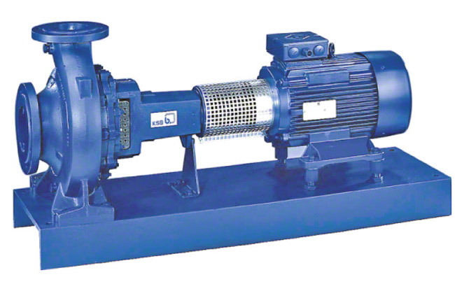
They serve to feed a steam generator such as a boiler or a nuclear reactor with a quantity of feed water corresponding to the quantity of steam emitted. Today, all boiler feed pumps are centrifugal pumps.

The design of boiler feed pumps regarding power input, material, type of pump and drive is largely governed by the developments which have taken place in power station technology. The trend in fossil-fuelled power stations is towards larger and larger power station units (> 1000 MW in 2011). This has led to boiler feed pumps with a drive rating of 30-50 MW. 

Until 1950, the average pressure in the outlet cross-section of the pump (discharge pressure of the feed pump) was in the 200 bar region. By 1955 the average discharge pressure had risen to 400 bar. The mass flow rates were in the region of 350 tonnes/h in 1950, compared to 3200 tonnes/h (in some exceptions up to 4000 tonnes/h) today. Boiler feed pumps operate at fluid temperatures of 160 to 210 ºC. In exceptional cases the temperature of the fluid handled may be higher still.

Feed pumps for 1600 MW nuclear power stations are constructed for mass flow rates of up to 4000 tonnes/h and feed pump discharge pressures of 70 to 100 bar.

Until 1950 approximately, boiler feed pumps were made of unalloyed steels; since then they have been made of steels with a chrome content of 13 - 14 %. This change of materials was made necessary by the introduction of new chemical feed water compositions. The development of highstrength, corrosion and erosion resistant martensitic chrome steels with good anti-seizure properties as well as the continuous development of all pump components (bearings, shaft seal, pump hydraulic system, etc.) paved the way for present-day boiler feed pumps with rotational speeds of 4500 to 6000 rpm.

The mass flow rates of centrifugal pumps rose rapidly in conjunction with the rise of unit outputs in power stations. Today's full load feed pumps for conventional 800 to 1100 MW power station units are constructed with four to six stages with stage pressures of up to 80 bar. Feed pumps for 1600 MW nuclear power stations are of the single-stage type.

Drive

In the case of conventional power stations above 500 MW full load feed pumps are increasingly driven by steam turbines. In most cases condensing turbines running at 5000 to 6000 rpm are used.

Electric motors usually drive part load feed pumps, both in fossil-fuelled and in nuclear power stations. Speed control of electrically driven feed pumps is effected by either fluid coupling  (e. g. variable speed turbo couplings) or by electrical closed-loop control systems by means of thyristors (up to a drive rating of approximately 18 MW in 2011).

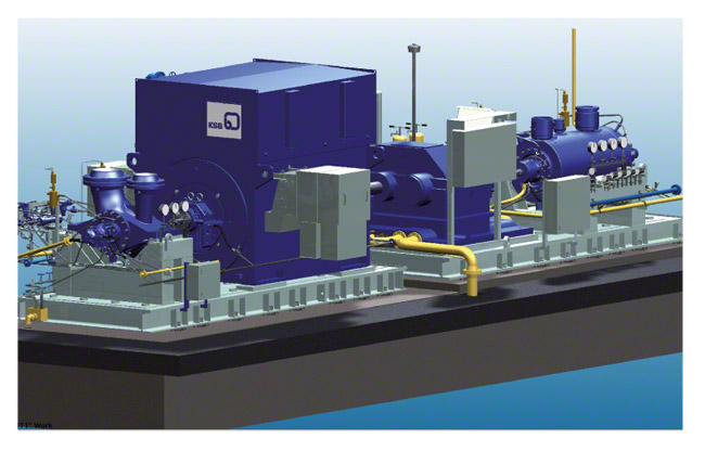
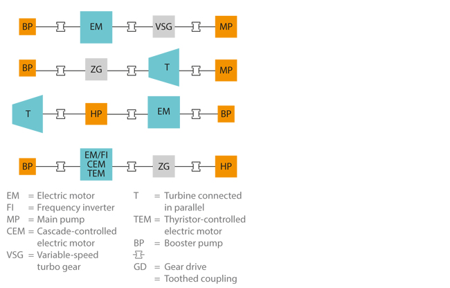
Four options of installing boiler feed pump drives are commonly used at present. See Fig. 1 Boiler feed pump

This is an embedded image

The low-speed booster pump is usually driven by the free shaft end of the turbine via a step-down gear or directly by the free end of the electric motor. See Fig. 2 Boiler feed pump

This is an embedded image

The single or double suction booster pump serves to generate the necessary NPSHR of the system for the high-speed boiler feed pump connected downstream. Fig. 3 Boiler feed pump

This is an embedded image

Design

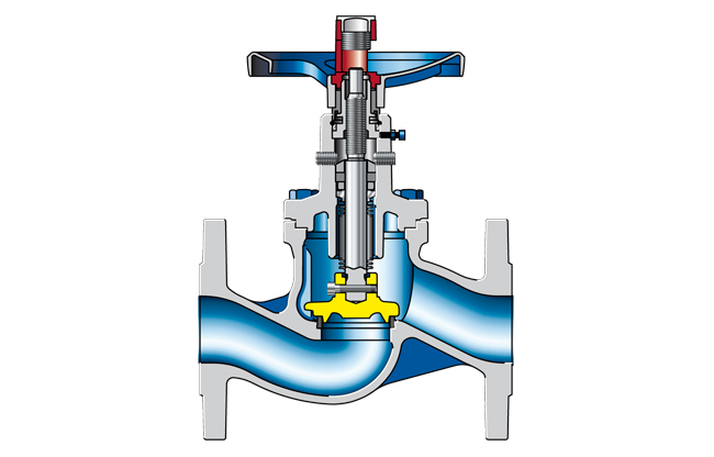
For conventional power stations boiler feed pumps are designed as:

This is an embedded image

This is an embedded image

These two types only differ in the construction of their pressure-retaining enclosure, which influences the manufacturing costs and ease of installation. There are no differences with regard to operating reliability and robustness also in abnormal operating conditions. The dimensions of the rotating parts and flow passages can be designed identically.

Two aspects of deciding between a ring-section and a barrel pull-out pump are described below:

  • The smaller the mass flow rate and the higher the pressure, the higher the material and manufacturing costs of barrel pull-out pumps. This does not apply to the same extent to ring-section pumps.
  • Barrel pull-out pumps have some advantages over ring-section pumps when it comes to repairing a pump installed in the system. If a rotor has to be replaced, the barrel (see Pump casing) can remain installed in the piping. This is significant with regard to the availability of a power station unit, if no full pump back-up is available or if pump replacement is very time-consuming

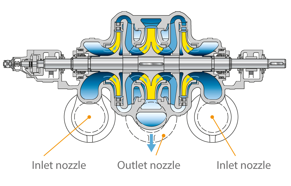
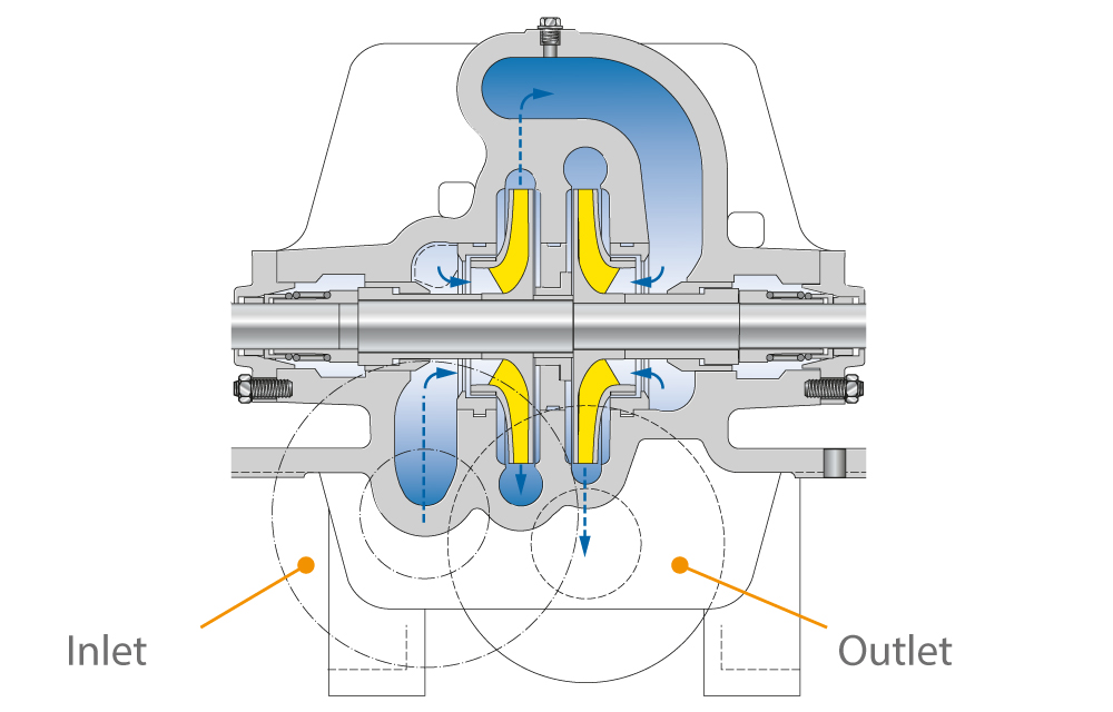
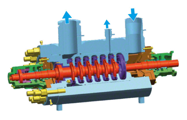
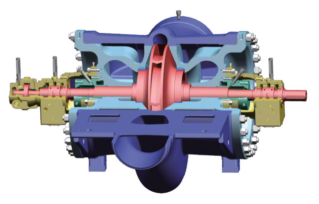
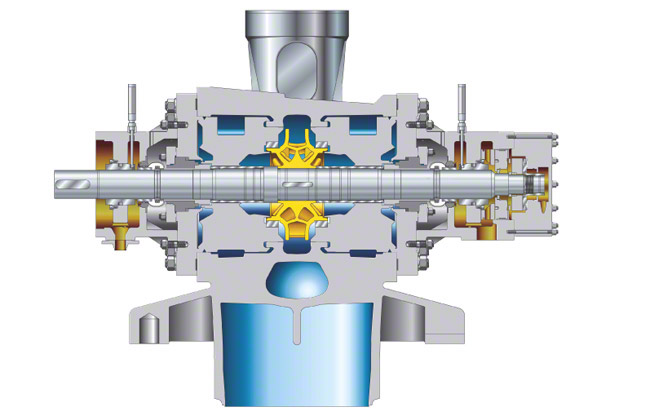
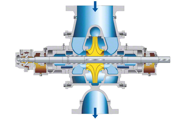
In the case of nuclear power stations, single-stage feed pumps with double-entry impeller (see Double-suction pump) and double volute casing are usually adopted. See Fig. 6 Boiler feed pump

This is an embedded image

Cast pressure-retaining casing parts are increasingly replaced by forged parts. As an example, such a feed pump could be designed with a flow rate of about 4200 m3/h and a head of about 700 m at a rotational speed of 5300 rpm. See Fig. 5 Boiler feed pump

Heads of reactor feed pumps are in the region of 800 m for boiling water reactors and 600 m for pressurised water reactors. The flow rates are about twice as high as those of a comparable boiler feed pump in a fossil-fuelled power station. 

Casing

For boiler feed pumps two factors have to be considered regarding the wall thickness of the casing: the pressure loads and the different temperature conditions it needs to withstand. These two criteria are satisfied by adopting a high-strength ferritic casing material which enables the wall thickness to be kept thin enough to avoid any overloads as a result of temperature fluctuations, yet of adequate thickness to guarantee the requisite safety against internal pressure.

Barrel casing 

  • The casings of barrel pull-out pumps and barrel casing pumps are usually made of unalloyed or low-alloyed ductile forged steel. Deposit welding is used on all surfaces in contact with the feed water to coat them with corrosion and erosion resistant material.  
  • In order to weld the pump into the piping, an adapter must be provided if the materials of the nozzles to be connected are from different material groups. 
  • The discharge-side (discharge pressure containing) barrel cover is fastened by means of large non-torqued studs. Sealing is provided by a profile joint which is pressurised purely by the prevailing pressure (of up to several 100 bar) without any external forces acting on it. See Fig. 7 Boiler feed pump

This is an embedded image

Ring-section pumps

  • The casings of ring-section pumps are preferably made of forged chrome or carbon steel plated with austenitic (iron solid solution) material.
  • The sealing element between the individual stage casings (see Stage) seals off by metal-to-metal contact, the individual casings being clamped together axially by tie bolts between the suction and discharge casings (see Pump casing). 
  • Thermal shocks causing various thermal expansions mainly lead to additional loads on the tie bolts and sealing surfaces of the stage casings.

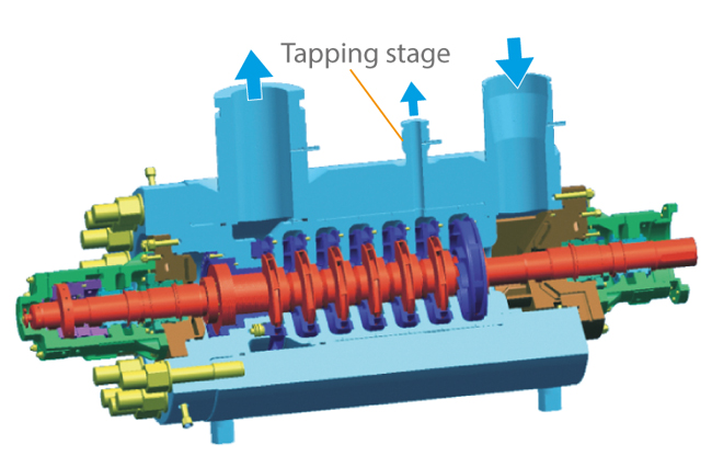
A common feature of barrel pull-out pumps and ring-section pumps is that the greater the wall thickness, the greater the thermal stress caused by thermal shocks, which in turn reduces the service life of the pump. The provision of injection water at a pressure situated between the suction and discharge pressure of the pump is a frequent requirement. This is taken care of by tapping water from one of the pump stages of both barrel pull-out pumps and ring-section pumps. 

Tapping a stage of a boiler feed pump

  • In the case of ring-section pumps, a partial flow at an intermediate pressure can easily be tapped through a tapping nozzle in one of the stage casings. See Fig. 5 Ring-section pump
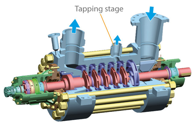
  • In the case of barrel pull-out pumps, the inside of the barrel is divided into three pressure zones so that a partial flow at the required intermediate pressure can be led off directly to the outside. See Fig. 4 Barrel pull-out pump
    The sealing function is taken care of by a profile joint between the discharge and the tapping pressure, and by a metal-to-metal joint between the tapping and the inlet pressure. See Fig. 7 Boiler feed pump
    Especially the profile joint allows a great degree of relative motion of the sealing surface, as required for any temperature shocks.

Rotor design 

The pump shaft of boiler feed pumps has a very small static deflection as the bearings are spaced as closely as possible, the shaft diameter is relatively large and the impellers are usually shrunk onto the shaft (for high performance). The pump shaft is generally insensitive to vibrations and runs smoothly (see Smooth running) without any radial contact during normal operation. The hub diameter at the back of the impeller is increased and the impeller inlet geometry is designed with a minimum diameter, so as to reduce the remaining axial forces (see Axial thrust) which have to be absorbed by the balancing device.

The rotors of single-stage reactor feed pumps are even stiffer than those of boiler feed pumps, and their static deflection is smaller than that of multistage boiler feed pumps.

Axial thrust balancing

Some impeller arrangements of boiler feed pumps for conventional power stations cause axial thrust at the impellers. See Figs. 10 to 12 Axial thrust

The magnitude of this axial thrust depends on the position of the operating point, on the characteristic curve, the rotational speed and the amount of wear on the internal clearances (see Controlled gap seal). Additional disturbing forces can arise in the event of abnormal operating conditions, e.g. cavitation

On larger boiler feed pumps the axial forces at the pump rotor are balanced by means of a hydraulic balancing device through which the fluid handled flows. The balancing device is often combined with an oil-lubricated thrust bearing (see Plain bearing). As this balancing device absorbs more than 90 % of the axial thrust, a relatively small thrust bearing can be used. The balancing device may comprise a balance disc with balance disc seat, or a balance drum or double drum with the corresponding throttle bushes.

Axial thrusts arising in reactor feed pumps with double-entry impeller (see Double-suction pump)  are balanced hydraulically; residual thrusts are absorbed by an oil-lubricated thrust bearing. See Fig. 6 Boiler feed pump

Balancing of radial forces on the pump rotor

Radial forces arise from the weight of the rotor, mechanical unbalance or hydraulic radial thrust. The radial forces are balanced by two oil-lubricated radial bearings as well as by throttling clearances through which the fluid handled flows in axial direction. Such throttling clearances are located at the impeller neck on the impeller inlet side, or in the case of multistage boiler feed pumps for conventional power stations on the discharge side of the impeller (interstage bush) and at the balance drum. If the rotor is in an off-centre position, a re-centring reaction force will be generated in these clearances, which largely depends on the pressure difference and the clearance geometry (LOMAKIN effect). 

The LOMAKIN effect is severely reduced when, due to abnormal operating conditions, the feed water in the clearance is not in a purely liquid phase (see Cavitation). 

The hydrostatic action of the clearances contributes more to reducing shaft deflection than the mechanical stiffness does. The system is designed in such a way that operating speed always remains well away from the critical speed of the rotor, allowing hydraulic exciting forces (particularly in low flow operation) to be absorbed in addition.
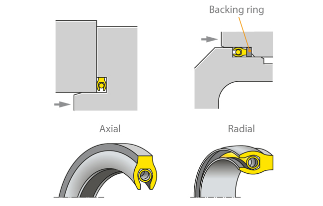
An additional diffuser or a double volute can reduce radial thrust. See Fig. 6 Volute casing pump

Shaft seal

Common shaft seals for boiler feed pumps are mechanical seals, floating ring seals and labyrinth seals. Gland packings are less common these days. (Also see Shaft seal). 

Warming up and keeping warm 

Transient or low flow operating conditions cause additional loads on boiler feed pumps. This leads to additional stresses and strains as well as to deformation of components with various consequences on their functionality.

Nowadays, almost all boiler feed pumps must be able to handle both cold starts (high-temperature shock loads) and semi-warm starts without any damage. In these start-up procedures hot feed water abruptly flows into the cold pump, which results in the inner components heating up much faster than the pressure boundary. Depending on the frequency of starts and the gradient curves of pressure and temperature (load cycles) this can shorten the service life of the pump.

On machines with particularly thick walls the heat will propagate more slowly in the thick-walled components, thus increasing internal stresses.

Contact between parts of the rotors and stator cannot, generally, be ruled out as narrow clearances are used as controlled gap seals. This applies to the impeller neck on the impeller inlet side, the discharge-side clearance between impeller, diffuser and interstage bush as well as the balancing device with several throttling clearances (depending on the design).

Critical operating conditions such as the formation of vapour bubbles, for example, cannot be completely avoided in the inlet line. Brief contact between the stator and the rotor leads to high unbalance forces in the narrow clearances. For this reason the material pairs have to be resistant not only to corrosion and erosion but also especially to wear (incorporating good anti-seizure properties). Profiled chrome steels and a special clearance geometry have proven successful.

In operating conditions with a very low or zero flow, e.g. in the turning gear mode of a turbine-driven boiler feed pump, temperature layers establish in the fluid handled, which may cause deformation of the rotors and, after a slight delay, also of the non-rotating components. Once the clearance gaps are closed the rotor will be subjected to a significantly higher friction moment, leading to overload of the turning gear and to standstill of the pump. In this case, the temperature will no longer be equalised at the rotor, which will further aggravate the rotor deformation.

This can result in several hours of downtime for the pump. Usually the only remedy is to let the machine cool down to reduce or eliminate the critical temperature layers and the deformation.

Several actions can be taken to optimise the thermal behaviour of the pump:

Avoid large differences in temperature in and on the pump

  • Thermally separate the cold areas (shaft seal area) from the area through which the hot fluid passes (hydraulic system and balancing device) by means of an insulation chamber system; provide a thermal seal to prevent convection flows and special thermosleeves.
  • Insulate the outside of the pump. 
  • Warm up or keep warm the pump by means of forced flow through the machine, usually via throttled pressure supply.
  • Temporarily or permanently interrupt the cooling water supply in the area of the mechanical seal (secondary circuit).
  • Limit the operating parameters for critical operating conditions (ΔT) (top/bottom of the barrel casing) and/or ΔT between casing and feed water.

Reduce the effects of large temperature differences  

  • Rotate the pump in stand-by mode using turning gear
  • Employ synchronised turning gear (minimise or prevent actual standstill time)
  • Drain water from critical thermal areas. 

Select good thermal characteristics when choosing shaft seals

  • Fit a non-contacting seal (floating ring seal)

The above measures are frequently used for barrel casing pumps (barrel pull-out pumps) as their outer dimensions, wall thickness, drive (turbine with turning gear) and operating modes are considered more critical than those of ring-section pumps. If possible, these measures are always automated to safeguard the availability of the pump set

Minimum flow valve

A minimum flow valve (automatic recirculation valve) ensures a minimum flow rate and thus prevents damage which could occur in low flow operation as a result of either an impermissible increase in temperature leading to vaporisation of the pump content or low flow cavitation.


Booster pump

Booster pumps serve to provide the required inlet head for a cavitation-free operation of the main pump installed downstream of the booster pump.

This is an embedded image


Boundary layer

In flowing fluids, the boundary layer is the area in the immediate vicinity of a solid wall where the velocity rises asymptotically (i.e. it approaches but never joins a given curve) from the value at the wall (no-slip conditions) to the value of the main flow which is not influenced by friction (free stream flow).

The boundary layer thickness is usually defined as the distance from the wall to the point where the flow velocity reaches 99 % of the free stream value. In the very thin boundary layer associated with free stream flows with high Reynolds numbers, a steep rise in velocity occurs perpendicular to the wall.

In contrast to the free stream flow which is practically frictionless (see Potential flow) the friction caused within the boundary layer by inertia and friction forces of the same order of magnitude must not be neglected because the. The friction forces also act on the wall causing frictional resistance.

The free stream and boundary flows influence each other: on the one hand, the free stream flow is deflected from the wall by the boundary layer's displacement effect and on the other, the free stream flow imposes a pressure pattern on the boundary layer which largely determines the boundary layer's development.

The flow in the boundary layer can be laminar als auch turbulent.  However, a laminar boundary layer is thinner than a turbulent boundary layer given the same free stream velocity. In the case of a turbulent boundary layer flow, the velocity profile is broader with a steep velocity gradient towards the wall, resulting in a much higher frictional resistance than in the case of a laminar boundary layer.

In the immediate vicinity of the wall, even a turbulent boundary layer always possesses a laminar sub-layer as all transverse movements, including turbulent fluctuations, must necessarily disappear at the wall itself.

In a flow around a body, a laminar boundary layer initially develops and grows in flow direction before becoming unstable after travelling a certain distance, and developing into turbulent flow under the influence of disturbances, e.g. wall roughness or turbulent fluctuations in the free stream flow. See Fig. 1 Head loss (refer to the Annex for an enlarged presentation) 

The boundary layer may become detached from the body (boundary layer separation). This phenomenon arises in flow regions where the static pressure which is imposed on the boundary layer by the free stream flow rises in flow direction.

The free stream flow is then deflected away from the wall by the boundary layer separation. A dead water zone characterised by eddies and vortices develops downstream of the point of separation. The flow velocities in this dead water zone are erratic in terms of magnitude and direction; part of this dead water flows backwards (recirculation effect).

There is no significant frictional resistance in the separation path downstream of the separation point. However, as a result of the dead water, an increase in the pressure resistance occurs which is far more significant than the decrease in frictional resistance. This means that the body's total flow resistance increases considerably in the event of boundary layer separation. Such flow separations should be avoided as far as possible by design measures and hydrodynamic streamlining equipment such as fittings, nozzles or diffuser elements

A particular type of flow separation involves so-called separation bubbles which develop in flow profiles where the boundary layer becomes turbulent immediately downstream of a laminar separation and re-attaches to the wall.

In curved ducts and rotating systems, the equilibrium in the free stream flow between the pressure forces on the one hand and the forces of inertia on the other hand is disturbed by the lower flow velocities in the boundary layer. The result is three-dimensional secondary flows.

The boundary layer plays an important role in flow through pipes. At the pipe inlet there is often a constant velocity distribution. A boundary layer is formed at the wall and its thickness increases with increased distance downstream from the pipe inlet. The core flow which has not yet been affected by friction is accelerated until, after a sufficient distance, the boundary layer has grown to its full width. From this point downstream, the pipe flow's velocity profile remains unchanged.

Branch fitting

Branch fittings are piping elements installed to allow a fluid flow to join or leave the flow in a main pipe. The magnitude of pressure losses or gains caused by a branch fitting is determined by the angle at which it connects different pipes, and the relationship between the volume flow rates in these pipes.

Breakaway torque

Breakaway torque refers to the maximum torque required to set interconnected stator and rotor components into motion. Instead of static friction forces, sliding friction forces will then apply.

Bubbler control

Bubbler control refers to a method applied by a bubbler control system, which is used to determine the fill level by measuring the pressure inside a bubbler tube. This method lends itself to chemically aggressive fluids.

Building management system

The term building management system encompasses computer-based controls and observation and monitoring of all relevant aspects of a building. The goal of a building management system is to automate process sequences and streamline monitoring and operation activities by networkingall functional units.

Bus

A wiring system and its associated control components are referred to as a bus in data processing. Buses exchange data between hardware components and are used in computers and their connections to peripheral devices (also see Communications systems). 

A distinction is made between serial and parallel buses.

Butterfly valve

The butterfly valve is a valve which controls the fluid flow by turning a disc (usually a 90° angle between the open and closed position (also see Valve).

Bypass

The term bypass means to circumvent or bridge. In centrifugal pump technology, it refers to a line that plays a key role in closed-loop control or as a balancing device. In the context of closed-loop control, it is possible to operate a centrifugal pump with a higher flow rate than that which is usable in the piping.

To this end, a bypass flow is branched off, which can either be routed back to the pump suction nozzle directly from the pump discharge nozzle through a narrow loop or reintegrated with the suction-side flow (after a delay) via different equipment such as a condenser and cooling unit.

When acting as a balancing device, the bypass is used to compensate axial thrust in boiler feed pumps.

Reasons to integrate a bypass: