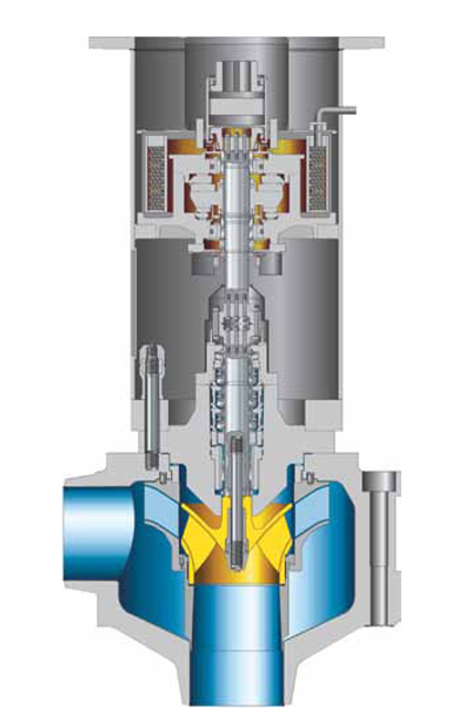
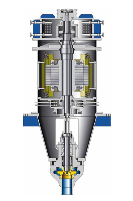
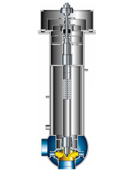
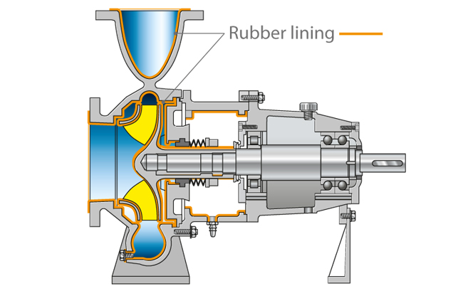
The reactor pump which acts as a reactor coolant pump is a
centrifugal pump, which circulates the coolant necessary to carry away the decay heat.
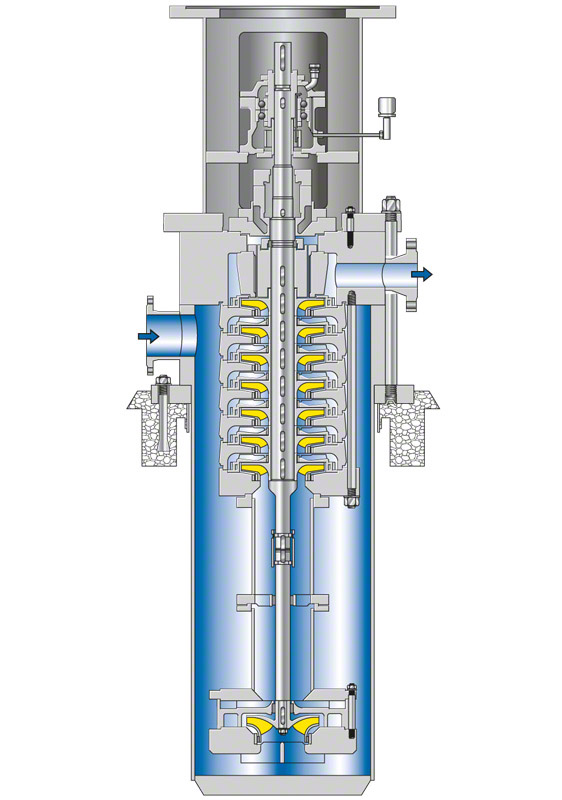
See Fig. 1 Reactor pumpDepending on the type of reactor plant, it is necessary to distinguish between pressurised, boiling and heavy water reactor pumps, and liquid-metal reactor pumps. Different designs of reactor pumps exist for the different reactor types.
Pressurised water reactors and heavy water reactors
The high
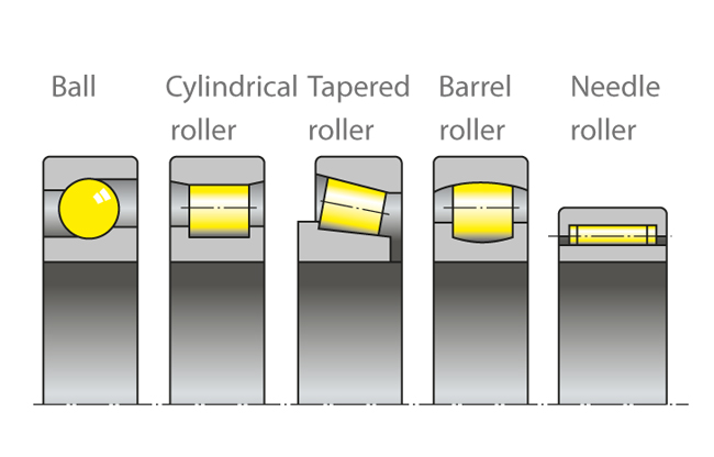
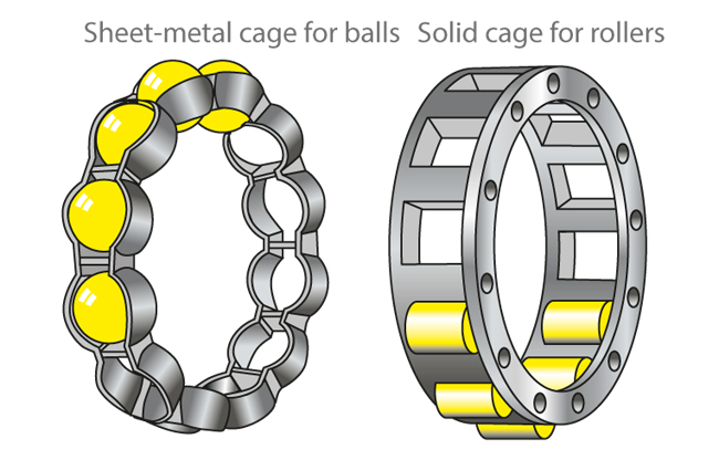
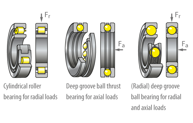
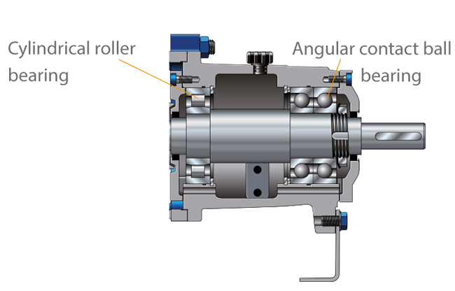
power input of pressurised water reactors and heavy water reactors necessitates the use of reactor pumps with shaft seal and integral bearing arrangement (axial, radial and
rolling element bearing) and integrated oil supply, see Fig. 1 Reactor pump, or of close-coupled reactor pumps with
drives in the form of conventional
electric motors.
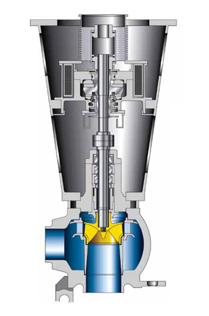
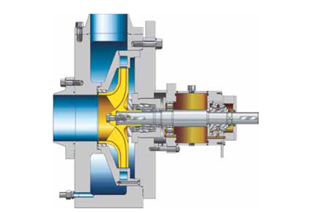
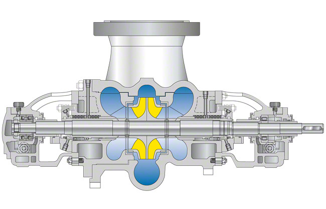
See Fig. 2 Reactor pumpThe
shaft seal consists either of several mechanical seals arranged in series, or of a combination of hydrostatic and
mechanical seals.
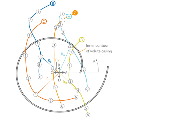
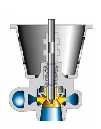
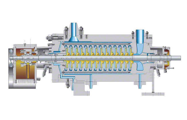
Depending on the support arrangement and on the type of suspension
forces and moments have to be absorbed by the
pump casing. This results in a number of different casing designs and wall thicknesses. The reactor pump casing is designed in the form of a spherical or pot-shaped casing, for example. The design pressure is 175 bar, and the corresponding
temperature 350 °C.
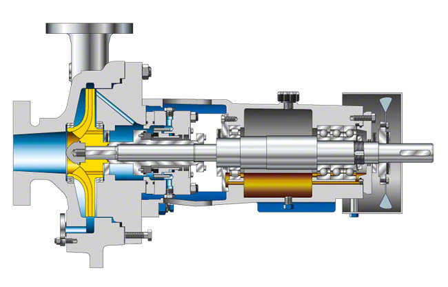
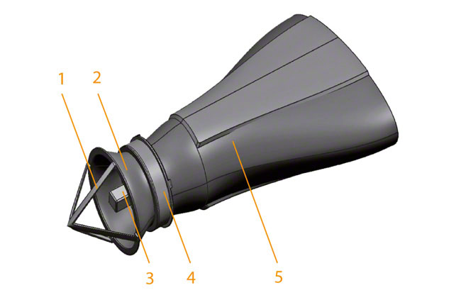
See Fig. 3 Reactor pumpBoiling water reactor
Two different reactor pump concepts are used for boiling water reactors. In the first concept, for reactor pressure vessels with built-in
jet pumps the reactor pumps are welded into the external
piping and are designed as driving water pumps, their casing mostly being a double volute (see
Volute casing pumps).
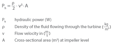
See Fig. 4 Reactor pumpTwo such driving water pumps incorporated in piping loops only handle approximately one third of the entire coolant flow. Instead, they drive the jet pumps which circulate the balance of the coolant flow within the pressure vessel. The driving water pumps are equipped with shaft seals and a conventional electric motor drive.
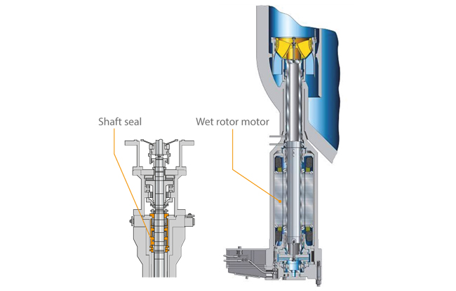
The second concept involves several reactor pumps accommodated in the reactor pressure vessel as
reactor internal pumps. These enable the coolant to circulate without the need for external piping. Whereas the driving water pumps are equipped with shaft seals and conventional electric motor drives, the insert pumps are also built with a wet rotor motor.
See Fig. 5 Reactor pumpThese electric motors are speed-controlled, enabling the pump flow rate to be adjusted and the reactor power to be controlled. The system pressure (design pressure) amounts to 90 bar, for example, and the design temperature to 300 °C.
Liquid metal cooled reactors
In the case of liquid metal cooled reactors, in which sodium is used as coolant, reactor pumps with a free fluid surface are used in the casing tube between the shaft seal and the pump impeller.
The free space is filled with an inert gas to prevent any sodium reactions, so that the shaft seal is required to protect against this protective gas and not against the liquid metal. The
pump shaft is guided by a liquid-metal lubricated hydrostatic bearing (see
plain bearing) situated immediately alongside the impeller.
The design pressure (system pressure) is 10 bar, and the corresponding temperature 580 °C. See Fig. 6 Reactor pump
Apart from reactor pumps, centrifugal pumps are also required in the auxiliary circuits and safety circuits of the various types of reactor. These include, for example, the volume control system, the decay heat removal system with high-pressure and low-pressure safety feed, the fuel storage pool, the secondary reactor loop and the water treatment system. See Figs. 7 and 8 Reactor pumps
The pumps in these types of circuits must meet specific requirements that usually do not need to be accounted for in centrifugal pump design.
The requirements for centrifugal pumps in auxiliary and safety circuits:
- Extremely high nozzle forces and moments must be transferred to the foundation (see Pump nozzle load).
- The pressure boundary must permit 100 % volumetric inspection and lend itself to detailed stress analysis.
- Very steep QH characteristic curves (flow rate, head) in order to implement extremely large operating ranges
- Low NPSHR values
- Due to the radioactivity in the fluid handled, any outboard leakage must be prevented (even in the case of temperature shocks).
- To minimise possible radiation exposure, the reactor pump must be easy to service in the event of maintenance inspection.
- Continued operation even in cases where the building is affected by earthquake or a plane crash, to avoid consequences such as flooding of the pump rooms, shutdown of the cooling water supply for mechanical seals and bearings, and a room temperature of over 65 °C with a relative humidity of 100 %