N

Net positive suction head

In physical terms the concept of the German term "Haltedruckhöhe" (retaining pressure head) is the same as the NPSH (net positive suction head) value. There may be a difference in the numerical values (ZS) between "retaining pressure head" and NPSH because different reference levels are defined for their calculation. See Fig.1 NPSH

In practice, only the NPSH value is used.

Neutral conductor

The neutral conductor is also referred to as the mid-point conductor in a single-phase alternating current system. It is connected to the centre or star point of the electrical power supply system and relays electrical energy.

Newtonian liquid

As per DIN 1342, the Newtonian liquid is defined as an isotropic, purely viscous liquid (see Viscosity), whose behaviour is subject to Newton's law of viscosity:

This is an embedded image

In fundamental terms, dynamic viscosity (η) depends only upon temperature.

Examples of Newtonian liquids are water and mineral oils from distillates that are handled by conventional centrifugal pumps.

Non-Newtonian liquids include sewage sludges and fine-grained mineral sludges (solids transport of sand, coal or ore) but also oils if their temperature is nearing the solidification point.

Pumping a non-Newtonian liquid by means of centrifugal pumps is sometimes only possible or efficient if the fluid handled has been heated. Such fluids' flow characteristics (see Pulp pumping)have an influence on pressure losses in the piping as well as the selection of centrifugal pumps.

Noise in pumps and systems

The noise emitted by pumps and systems is caused by vibrations in the piping and the pump casing. These vibrations interact with the surrounding air and are perceived as airborne sound.

Transient flow and the pressure fluctuations associated with it produce this effect. The fluctuations occur when energy is transferred via the impeller vanes to the fluid handled. The finite number of vanes leads to periodic pressure fluctuations with amplitudes of varying intensity. Since the flow encounters continually increasing static pressure, the boundary layers are at great risk of separating. The flow pattern of the fluid flowing around the vanes as well as flow separation make the flow in a centrifugal pump transient.

For single-stage volute casing pumps comprising a few basic components, these transient flows are the main source of noise apart from that generated by the drive of the centrifugal pump.

Multistage pumps with balancing devices also produce substantial turbulence noise (see Fluid mechanics) resulting from the characteristically high delivery heads of the individual stages, as can higher pressures when they are relieved in balancing devices, for example.

The aforementioned sources of noise relate to pumps and systems operated in the absence of cavitation. When cavitation occurs in a pump or valve the level of noise produced is considerably more pronounced. Cavitation noise typically sounds like a high-pitched crackling and transitions to an intense rattling sound when the effect intensifies (i.e. lower NPSH).

Cavitation noise contributes to the overall noise emitted by pumps and systems and necessitates further outlay for any noise control measures that are required. It can also be used, however, for detecting and - by using suitable measuring equipment and analysis methods - acquiring information about the intensity and erosive potential of cavitation conditions.

The trend toward higher rotational speeds exacerbates the problem of noise in centrifugal pumps, which leads to smaller, more powerful machines (increased power density). Adding to this is the fact that better use is being made of materials to reduce wall thickness. Doing this, however, also makes the pumps more conducive to vibrations.

The influences of individual components on the overall noise emitted by a pump set are complex and hinge on many factors. See Fig. 1 Noise in pumps and systems

This is an embedded image

Characteristic sound power levels can be assessed in accordance with VDI 3749, which provides emission values for different technical sound sources.

The influential effect of foundations (see Pump foundation),  buildings (with extended periods of heavy reverberation), piping, and adjacent machines and systems is particularly difficult to estimate.

Guidelines and technical codes exist for measuring noise (see Noise measurement).

Statistical analyses have revealed that, depending on the type of pump and in non-cavitating operation, 10-9 to 10-6 of a centrifugal pump's power input is converted to sound power, which may take the form of solid-borne, air-borne and liquid-borne sound. See Fig. 2 Noise in pumps and systems

This is an embedded image

Noise control

The most critical active sound-absorbing measure for noise control is the correct selection of the pump itself, which must be designed for the task in question and have the correct size.

The sound of a centrifugal pump varies in intensity along its H/Q curve depending on the operating point. To conserve energy and minimise noise, pumps should generally be run at the operating point that provides optimum pump efficiency. Noise is usually lowest when the pumps are operated at a speed near BEP.

Passive sound-absorbing measures are a necessity when centrifugal pumps are used in applications with stringent noise restrictions, and include expansion joints in the piping installation of the pump set on rubber-metal or spring mounts, in sound enclosures and insulated rooms in which pump sets are operated with special sound-proofing or sound-dampening panels.


Noise measurement

Noise measurement is conducted to define a noise emitted by a source (also see Noise in pumps and systems) and is therefore also referred to as sound or acoustic measurement. Different measuring methods can be applied to this end and are described in several standards.

Standards for noise measurement

  • DIN EN ISO 20361
    (Liquid pumps and pump units)
  • DIN 45635 B1
    (Measurement of noise emitted by machines, air-borne noise emission, enveloping surface method)
  • DIN EN ISO 3744
    (Determination of sound power levels and sound energy levels of noise sources using sound pressure (accuracy class 2) - Engineering methods for an essentially free field over a reflecting plane)
  • DIN EN ISO 3746
    (Determination of sound power levels and sound energy levels of noise sources using sound pressure (accuracy class 3), survey method)
  • DIN EN ISO 9614-2
    (Determination of sound power levels of noise sources using sound intensity; Part 2: Measurement by scanning) 

These standards not only define key sound terms, but also provide useful information about measuring instruments and conditions, performing and evaluating sound measurements, and measurement uncertainties (also see Metrology). In so doing, they establish the basis for determining the noise dissipated by centrifugal pumps into the surrounding air using standardised methods to obtain comparable results. Values determined in this manner can be used to compare similar and different machines, assess noise emissions (see Federal Immission Control Act), and devise appropriate noise control measures.

Nominal diameter

The nominal diameter is referred to as the pipe diameter or the mating dimension of a valve (with valves this is usually referred to as the nominal size). In combination with the nominal pressure the approximate inside diameter is specified in millimetres to ISO 6708 in the form of a dimensionless figure, preceded by the designation DN (DN 100).
The table "Nominal diameters to DIN 2402" provides an overview. It does not specify numerical values. See Fig. 1 DN

Nominal pressure

The term nominal pressure was changed to PN, as this term was only vaguely associated with permissible pressures and therefore considered misleading. See Figs. 1, 2 PN

Nominal speed

Nominal speed (nN) is a suitable, rounded speed value for classifying the speed range (see Nominal value). Nominal speed is no longer the speed previously agreed on in the supply contract, but typically a deviating, rounded, and generally applicable speed such as 2.900, 1.450, or 980 min–1 (rpm) for a mains frequency of 50 Hz or 3.500, 1.750, 1.180 min–1 (rpm) at 60 Hz.

Nominal value

The nominal value as defined by DIN 40200 is a suitable rounded value of a quantity for designating or identifying a component, device or equipment. The following application areas can be categorised using the nominal value of a quantity.

Application areas

  • Nominal diameter (DN), e.g. DN 100 
  • Nominal pressure  (PN), e.g. PN 16 
  • Nominal speed (nN), e.g. nN = 2,900 min–1 (rpm)
    (rated speed)
  • Nominal voltage, e.g. 230 V
    Voltage of a mains supply
  • Rated voltage (of equipment) from the manufacturer for a defined operating condition of a component, device, or piece of equipment

The quantity actually used does not need to be identical to the nominal value but can approximate it. There are scenarios in which the nominal and rated value are one in the same.

In this case, the term that applies must be defined. A synchronous motor designed for a speed of 3,000 min-1 (rpm) at 50 Hz will, at this frequency, always run at 3,000 min-1.

The user views this speed as well as that of the machine driven directly by the synchronous motor as the "nominal speed" because the rounded numerical value for designation and identification purposes is suited to daily use. This speed is also regarded as the "rated speed", since it establishes the basis for designing and rating the motor. It is in this context that the nominal speed is no longer the speed agreed on in the supply contract (as previously), but a classification speed (e.g. 2,900 min–1 (rpm)).

NPS

NPS stands for Nominal Pipe Size and refers to the nominal diameter, which for threaded pipes is usually stated in inches (see DN).

NPSH

The term NPSH is the abbreviation of "net positive suction head" and is an important factor in evaluating the suction characteristics of a centrifugal pump. It allows a prediction to be made regarding the safety margin required to avoid the effects of cavitation during operation.

In the DIN EN ISO 17769-1 standard the German term "Haltedruckhöhe (retaining pressure head)" is used as a synonym for NPSH. As different reference levels are defined for the two terms, their numerical value can differ by zs (difference in geodetic head between reference levels s and s'). In practice, only the NPSH value is used.

As the fluid flows through the centrifugal pump's impeller the static pressure relative to the pressure upstream of the impeller – will drop, especially at the inlet to the vane passage. The extent of the pressure drop depends on the rotational speed, the fluid density, and viscosity, the impeller’s inlet geometry, the operating point and the velocity profile of the approach flow.

In order to avoid cavitation or to limit it to an acceptable level, the pressure upstream of the impeller must exceed the vapour pressure level of the fluid handled by a specified minimum margin. Assessing the likelihood of occurrence, extent and impact of cavitation in a centrifugal pump requires comparison of two NPSH values: the NPSH required by the pump NPSHR and the NPSH available in the system, NPSHA.

The system's NPSH, i.e. NPSH available (NPSHA) is defined as

This is an embedded image

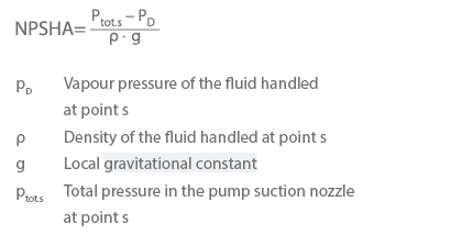
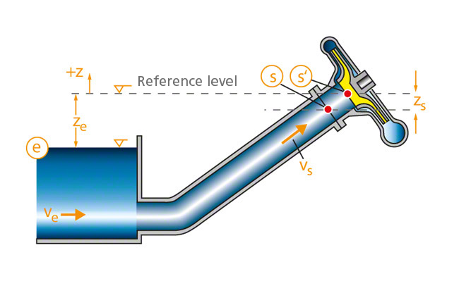
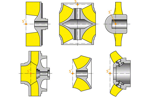
Point s refers to the suction nozzle's centre. If the pump's design does not feature a suction nozzle as is the case with in-line pumps with welded-in pipes (i.e. welded-in pumps) or submersible pumps with bellmouths, a location s which corresponds to the point s in the suction nozzle's centre must be defined and clearly specified when specifying the NPSHA value. See Fig. 1 NPSH

This is an embedded image

The total pressure at point s can be expressed as:

This is an embedded image

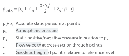
The reference point s' for the NPSH value is the impeller’s centre, i.e. the intersection of the pump shaft axis and a plane situated at right angles to the pump shaft passing through the outer points of the vane leading edge. See Fig. 2 NPSH

This is an embedded image

The system's NPSH is thus established as follows:

This is an embedded image

Inserting the values at the system's inlet cross-section gives:

This is an embedded image

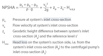
The head loss also includes any entry losses and pressure drops across valves and fittings etc.

NPSH required by the pump (NPSHR)

The definition of the NPSH required by the pump (NPSHR) is similar to that of the system's NPSH, i.e. the symbols in brackets have the same meaning:

This is an embedded image

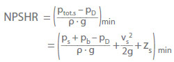
However, a significant difference is that the sum of the parameters defined by the terms in the brackets must not fall below a minimum value (min) specified for a given pump and application.

If this condition is not met, the occurrence of cavitation cannot be ruled out.

When specifying the NPSHR, it is also necessary to provide information on the relevant cavitation criterion. Criteria include:

  • Incipient cavitation, NPSHi
  • A certainextent of the cavitation zone on the vanes
  • Start of head drop as a result of cavitation (NPSH0)
  • Cavitation-induced head drop by 3 % (NPSH3)

The first three criteria are less common, and providing evidence for NPSHi requires demanding and expensive testing. For this reason, it is commonly agreed that NPSHR = NPSH3.

The cavitation criteria listed above and their related NPSH values are dependent on the operating point. See Fig. 3 NPSH

This is an embedded image

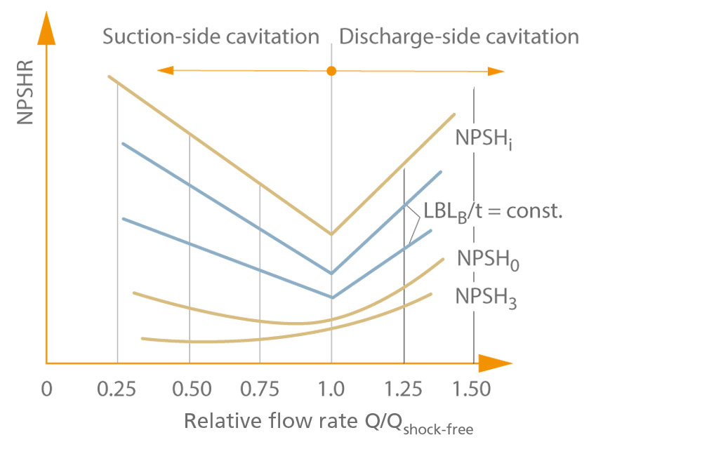
The illustration shows the curves for NPSHR of a specific impeller as a function of the relative flow rate The parameters shown are the cavitation phenomena, e.g. the length (Lcav) of the resulting bubble trail (cavitation zone) in relation to the vane spacing or pitch (t) (see Vane cascade).

If the NPSHA curve is also displayed in the diagram, it is possible to determine the type of cavitation to be expected as a function of flow rate.

The upper curve (NPSHi) indicates incipient cavitation. If NPSHA is higher than NPSHi, cavitation will not develop and the impeller will rotate without the formation of bubbles. The lower the NPSHA value drops, the longer the bubble trail (cavitation zone) will become.

From a minimum level represented in the graph as the intersection of the lines denoting suction-side and discharge-side cavitation, the bubble trail length will increase under low-flow/overload conditions at a constant NPSHA. The flow rate at this minimum level corresponds to the flow direction of shock-free entry which causes the lowest increases in fluid velocity on the pressure side and suction side of the vane. It is therefore referred to as the shock-free flow rate (Qshock-free).

If the flow rate (Q) is lower than the shock-free flow rate (Qshock-free), then cavitation will develop on the vane's suction side; if the flow rate is higher than the shock-free flow rate, then cavitation will develop on the vane's pressure side.

Establishing NPSHR is largely a matter of testing, in particular when:

  • Converting the NPSH of the pump from one rotational speed to another
  • On similar pumps, converting NPSH from one pump size to another
  • Converting NPSH from one fluid to another (in particular if the fluid contains dissolved or undissolved gas) (see Gas content of fluid handled

A centrifugal pump's operating point can only be operated at continuously if:

This is an embedded image

The following relationship exists between the NPSH value and the German concept of "Haltedruckhöhe” (retaining pressure head) which is no longer used:

Retaining pressure head of the system
HHA = NPSHA – zs

Retaining pressure head of the pump
HP = NPSHR – zs

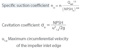
In the case of horizontal pumps, there is no difference in height (zs = 0) between the reference points for NSPH and "retaining pressure head", making the two terms identical. The following coefficients are sometimes used in connection with the NPSH value:

This is an embedded image

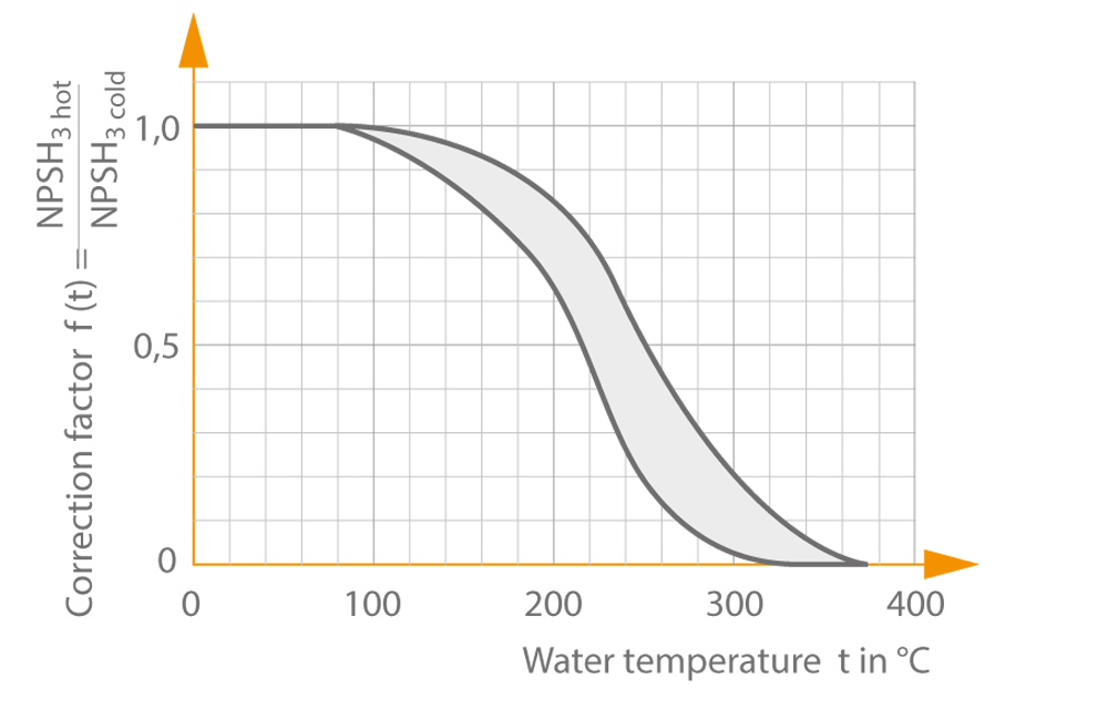
When hydrocarbons or high-temperature water are handled, the NPSH3 value measured is lower than that measured for cold water. This means that the required NPSH value for hydrocarbons or hot water can actually be reduced when performing acceptance tests with cold water:

  • Hydrocarbons in accordance with HI
    (standards laid down by the Hydraulic Institute, New York)
  • Hot water See Fig. 4 NPSH

This is an embedded image


NTC resistor

The NTC (Negative Temperature Coefficient) resistor is also referred to as the NTC thermistor and is a thermistor with a negative temperature coefficient. Its resistance value increases as temperature decreases.

A PTC resistor is used to record temperature, especially during soft starting, in order to limit the starting current.

Number of poles

The number of pole pairs (p) or number of poles for an asynchronous motor determines the motor's synchronous speed:

This is an embedded image

Two-pole and four-pole asynchronous motors are typically used for centrifugal pumps.The rotational speed of these motors can be varied using frequency inverters. 

The full-load speeds of asynchronous motors are approximately one percent below the synchronous speeds for high-output motors and up to six percent below the synchronous speeds for low-output motors, whereby synchronous speeds are almost reached at no load. 

This is an embedded image


Number of starts per hour

The number of starts per hour (Z) determines the maximum number of starts that should be performed by a pump set in an hour. This number influences the size of the accumulator and is defined in consideration of the motor heating and contact wear data provided by the supplier of the electric motor (also see Accumulator).