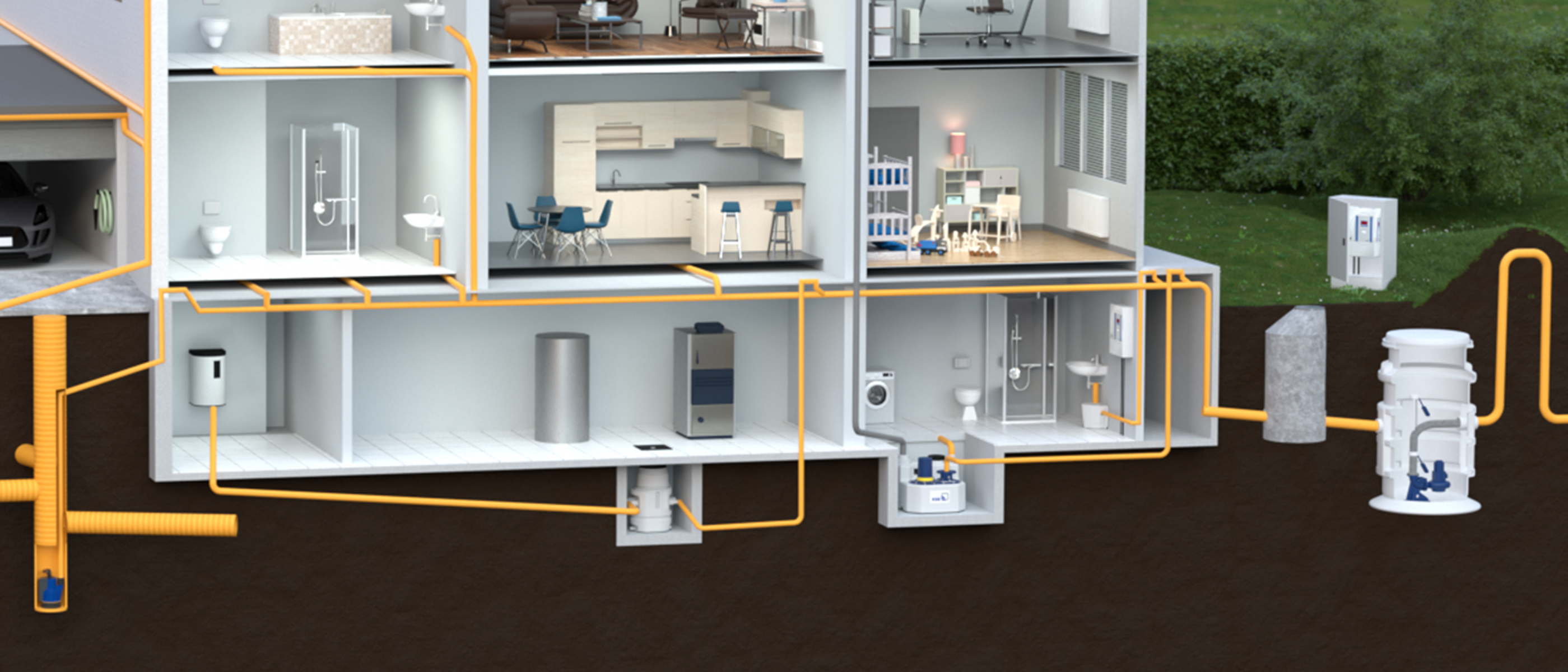
Pump sump with submersible motor pumps
8 min read

Correctly measuring the fill level in the pump sump

Stormwater or waste water collects in pump sumps, from where it can easily be pumped off. Naturally, the sumps should neither overflow nor be too empty to prevent the submersible motor pump installed on the sump floor from running dry and becoming damaged. How can this be avoided? Read on to find out more about the correct fill level in the sump and get to know common measurement methods.

Stormwater or waste water collects in pump sumps, from where it can easily be pumped off. Naturally, the sumps should neither overflow nor be too empty to prevent the submersible motor pump installed on the sump floor from running dry and becoming damaged. How can this be avoided? Read on to find out more about the correct fill level in the sump and get to know common measurement methods.

What exactly is a pump sump? And what is its role in the drainage of buildings? 

A pump sump is usually covered, made of concrete (or plastic) and installed on the property outside the house, for example in the front yard. Initially, the sump serves to centrally collect stormwater and/or waste water, so the water can be lifted above the flood level and pumped off.

What goes in must come out

This means the sump is only filled with water temporarily. Since the water collected cannot percolate through the concrete or plastic, a pump has to transport the collected water from the sump to the central waste water line (sewer), where it will be discharged. For this purpose, a fully floodable submersible motor pump is installed at the floor of the sump, that draws in the water at the bottom and pumps it upwards into the waste water line.

If the sump has been filling with water for a specific period of time and the water reaches a defined fill level, the pump starts up automatically and pumps off the water. The water level sinks, and the pump keeps running until the level falls to a defined minimum. The important thing is: Submersible motor pumps should not "run dry"; they should stop before the sump is drained completely. Otherwise, the pump draws in air, and the motor will be surrounded by air rather than by the fluid cooling it down.

The key is to measure both the maximum and the minimum fill level in the sump to prevent overflow and avoid dry running of the pump. How can this be measured accurately?


Schematic of a pump sump with installed submersible motor pump

As can be seen from the illustration, the pump installed on the pump sump floor transports the waste water above the flood level, from where it is drained into the sewer system by gravity flow.

Various principles of fill level measurement

A number of different methods can generally be used to measure the fill level of liquids in vessels or tanks. All of them have got advantages and disadvantages – and some are more suitable for certain applications than others. A general distinction is made between continuous measurement and time point measurement as well as between contactless measurements and measurements for which a sensor is in contact with the fluid. Below we will introduce the most important measurement methods.

Measurement with float switches

This relatively simple measurement method is likely to be the most widely used in building services: A float switch with integrated contacts floats on the liquid in a sump. When a defined level is reached, the contact is activated and transmits a signal to the pump control unit. When the level sinks again, the contact responds in the other direction.

Float switches can be used as digital level transmitters. Alternatively, the hysteresis between the switching levels of the float can be used. For single pumps, a mechanical float is suitable for starting and stopping the pump directly. For systems with stand-by pumps a control unit is required to control the pump with float switches. Float switches can be employed in potentially explosive atmospheres, provided the float switch and the control unit are suitably certified.

The benefit of float switches: This measurement method is simple and cost-efficient; it is based on a simple mechanical principle.

Schematic of a dual-pump station: Draining via two float switches

Draining via float switches. Here at the example of a dual-pump station with two float switches. The pump that is started up first is the base load pump. To ensure equal distribution of pump operating hours, the pumps are automatically alternated after each pumping cycle.

A = Base load float switch

B = Peak load float switch

C = High water float switch (optional)

1 = Both pumps OFF

2 = Base load pump ON

3 = Both pumps ON

4 = High water alert

Measurement with float switches without use of hysteresis

For float switches without use of hysteresis only one switching point is used. This means that at least two floats have to be fitted – one a the bottom for stopping the pump, and one at the top for starting up the pump. The benefit of this measurement method is that lower measurement levels can be realised.

Schematic of a single-pump station with draining via two float switches without use of hysteresis

Draining via float switches without use of hysteresis.Example of a single-pump station with draining via two float switches without hysteresis

A = Float switch OFF

B = Base load float switch

C = High water float switch (optional)

1 = Pump OFF

2 = Pump ON

3 = High water alert

Measurement with float switches without use of hysteresis

For float switches without use of hysteresis only one switching point is used. This means that at least two floats have to be fitted – one a the bottom for stopping the pump, and one at the top for starting up the pump. The benefit of this measurement method is that lower measurement levels can be realised.

Schematic of a single-pump station with draining via two float switches without use of hysteresis

Draining via float switches without use of hysteresis. Example of a single-pump station with draining via two float switches without hysteresis

A = Float switch OFF

B = Base load float switch

C = High water float switch (optional)

1 = Pump OFF

2 = Pump ON

3 = High water alert

Hydrostatic fill level measurement via pneumatic measurement or bubbler control

his method is based on a simple physical principle: Every fluid has got its individual weight, determined by gravity and density. The higher the fill level, the higher the pressure exerted by the fluid on the tank floor. The hydrostatic pressure is directly proportional to the filling level of the fluid. The pressure is measured via a pressure bell immersed in the fluid. The measurement is transmitted to the sensors via a bubbler tube or pressure hose, and analysed. The benefit of this measurement method: It is neither influenced by contamination of the fluid nor by foam on the surface, turbulences or internal parts in the pump sump.

Pneumatic pressure measurement

Closed systems can only be used when the measurement system is absolutely tightly sealed. If air can enter the measurement system through a leakage point, a pressure drop will result in malfunction of the device. The closed pressure bell in the fluid seals the measurement system at the measurement point.

Bubbler control

In bubbler control, a small compressor is used to feed air into the system. The pressure in the measurement system (pressure hose) remains constant. Only a change in fill level will lead to a pressure change in the measurement system. This method is suitable for chemically aggressive fluids as well as for fluids containing faeces, for example, because the sensor is "kept free" by the bubbles; no solids can deposit on the sensor.

Level measurement with an open pressure bell: Schematic of a pump sump with installed pump and pressure bell

Schematic of a pump installed in a pump sump. Level measurement via pneumatic measurement or bubbler control. The additional float switch for high water alert is optional.

A = User-defined switching levels in mm

B = Reference point for level measurement

C = Redundant high water float switch (optional)

1 = Pump OFF

2 = Pump ON

3 = High water alert

Analog level measurement with a level probe

Essentially, level probes (also called immersion probes or level sensors) are specially designed pressure sensors. Such sensors are used for hydrostatic fill level and liquid level measurements in tanks, wells, sumps and boreholes. A level probe is directly immersed in the liquid to be measured and guided as close as possible to the bottom. This is where it measures the hydrostatic pressure, from which the current fill level, i.e. the water column above, can be directly derived. The hydrostatic pressure of the liquid column causes an expansion at the pressure-sensitive sensor element that converts the measured pressure into an electric 4 to 20 mA signal.

Level measurement with analog measurement: Schematic of a pump sump with installed pump and a high water float switch

Schematic of a pump installed in a pump sump. The fill level is measured with a 4...20 mA immersion probe. The additional float switch for high water alert is optional.

A = User-defined switching levels in mm

B = Analog IN

C = +24 V

D = Ground (GND)

E = Redundant high water float switch (optional)

1 = Fill level at 4 mA

2 = Pump OFF

3 = Pump ON

4 = High water alert

5 = Level at 20 mA

Conclusion

When systems for draining buildings are planned, sumps and pump stations play a decisive role. Selecting the right measurement method forms the basis of reliable long-term operation. Apart from the measurement method, a myriad of other factors has to be considered, e.g. the frequency of starts of the pumps, the fluid handled, the sump volume, or the inlet and outlet volume. It is an exciting and technically demanding topic.

Suitable products

AmaDrainer 4 / 5/AmaDrainer 80 / 100

AmaDrainer 4 / 5/AmaDrainer 80 / 100

AmaDrainer 4../5..: Vertical single-stage fully floodable submersible motor pump in close-coupled design, IP68, with or without level control, max. immersion depth: 7 m. AmaDrainer 80/100: Vertical single-stage fully floodable submersible motor pump in close-coupled design, IP68, with or without level control, max. immersion depth: 10 m.

AmaDrainer Box/AmaDrainer Box Mini

AmaDrainer Box/AmaDrainer Box Mini

AmaDrainer Box:Stable above-floor plastic collecting tank or impact-resistant underfloor plastic collecting tank, with floor drain and odour trap, both with AmaDrainer submersible motor pump starting and stopping automatically and swing check valve AmaDrainer Box Mini:Reliable and compact grey water lifting unit in a modern design with activated carbon filter meeting hygiene requirements and with shower connection as standard; complies with EN 12050-2.

Compacta

Compacta

Floodable single-pump sewage lifting unit or dual-pump sewage lifting unit for automatic disposal of waste water and faeces in buildings and building sections below the flood level.

MiniCompacta

MiniCompacta

Floodable single-pump sewage lifting unit or dual-pump sewage lifting unit for automatic disposal of domestic waste water and faeces in building sections below the flood level.

LevelControl Basic 2

LevelControl Basic 2

Level control unit for controlling and protecting either one or two pumps. DOL starting up to 4 kW, star-delta starting up to 22 kW. Higher ratings on request.

Stay up to date with the KSB Newsletter.

Want to make sure you never miss the latest news? With the KSB Newsletter you will receive information on our products and solutions, current promotions and events as well as fascinating insights into the world of KSB.

Don’t hesitate to contact us.

Would you like further information on KSB? Or have you got any questions surrounding our pumps, valves, services and spare parts? Just contact us. We would love to talk to you.